Product Description
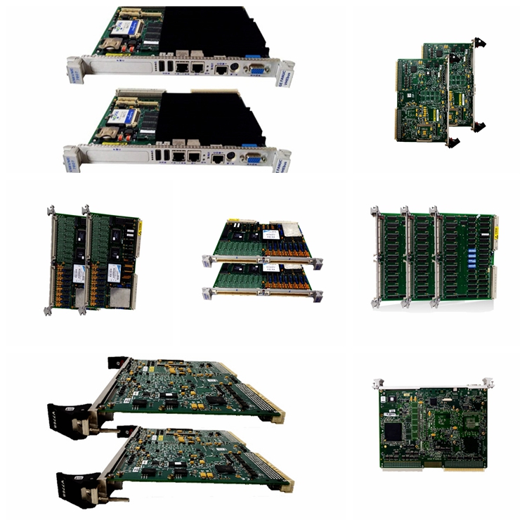
The GE Gate Lead Adapter Board DS200GLAAG1A features two terminal blocks with a maximum of 6 wires, two 2-pin connectors, and two 4-pin connectors. The DS200GLAAG1 also contains 2 LEDs. The terminal blocks on the GE Gate Lead Adapter Board DS200GLAAG1A are used to provide a connection for the wires that send and receive signals on the board. Each terminal block can hold up to three signal wires. When you are in the process of replacing the board you must follow a process to reduce the opportunity for connecting the signal wires to the wrong terminal connectors.
When you first setup the original DS200GLAAG1A you will find a description of the purpose of each terminal connector and what wire to attach to each one. This results in the board being wired to perform the processing functions you require in the drive. However, when you replace the board the task only involves matching the wire connections from the original board on the replacement board. Inspect the original board and notice that each terminal connector has a letter and number designator.
Obtain tags, cards, or other paper to write down the designator to which each wire is attached. Affix the paper to the wire and do the same for all the wires attached to the terminals. Then, use a small screwdriver to loosen the wires in the terminal and remove the wires. Do not remove the paper attached to the wires with the identifying information. Attach the wires to the same terminals on the replacement board.