Contact Us
Contact: YMGK Industrial Control
Phone: +86 18059884790
E-mail: plc66@qq.com
Add: No. 9, 14th Floor, Building 42, Hongshan Lake Road, North Street, Xixiu District, Anshun City, Guizhou Province, China
- Warehouse: Spot
- Warranty: 365 days
- Quality: Original module
- Condition: New / Used
- Shipping method: Courier delivery
- Contact person: Linda
- Contact number: +86 18059884790
- WeChat:18059884790
- E-mail: plc66@qq.com
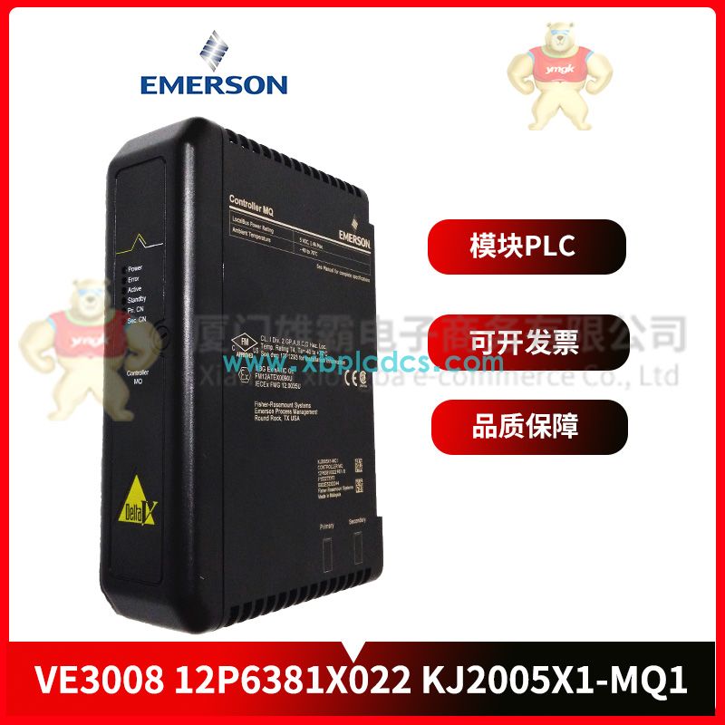
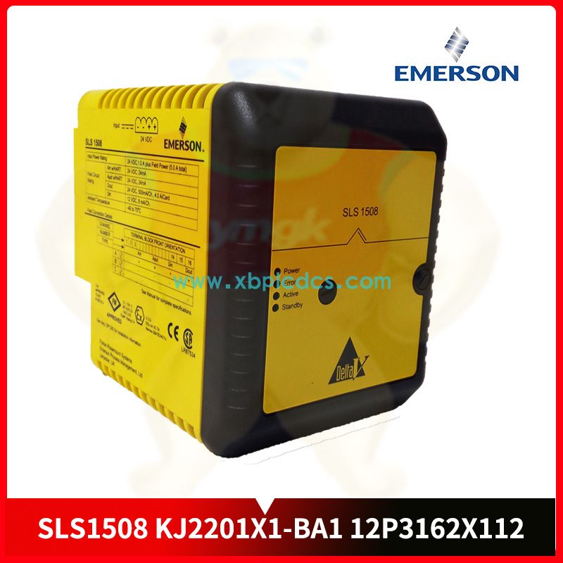
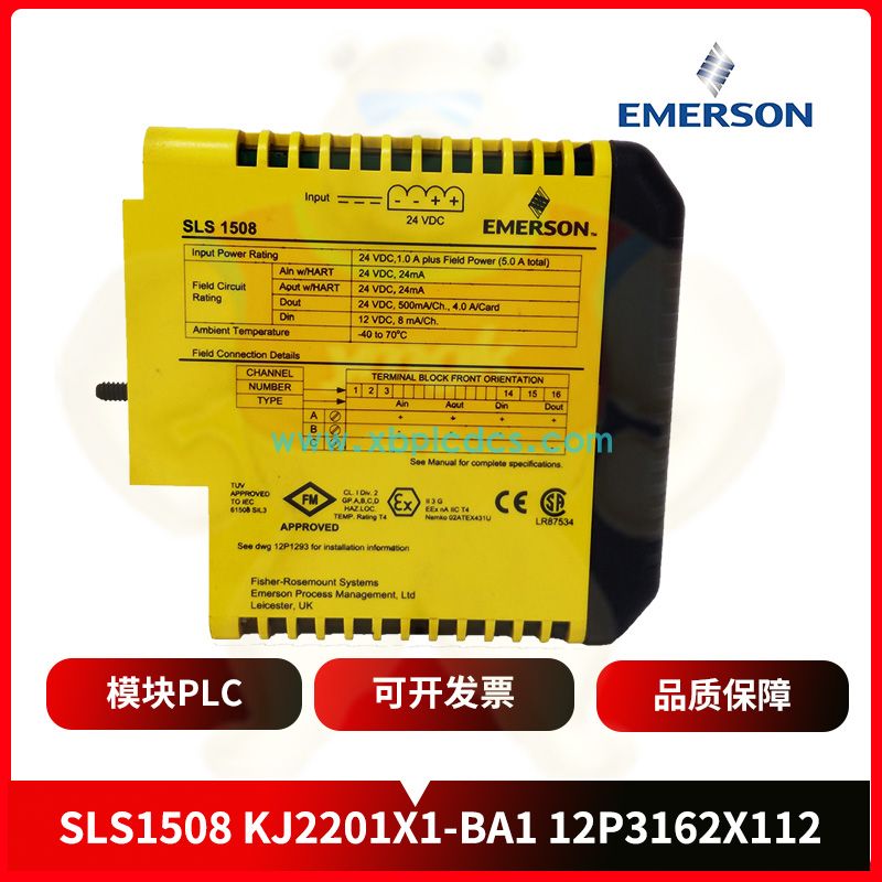
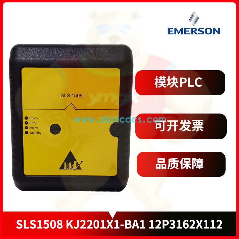
SLS1508 Controller module EMERSON
1. Central processing unit
The central processing unit (CPU) consists of a controller, an operator and registers and is integrated into a chip. The CPU is connected to memory, I/O interface, programmer and power supply through data bus, address bus, control bus and power supply bus.
The CPU of small PLC uses 8 bit or 16 bit microprocessor or single chip microcomputer, such as 8031, M68000 and so on, this kind of chip price is very low; The CPU of medium-sized PLC uses 16 bit or 32 bit microprocessor or microcontroller, such as 8086, 96 series microcontroller, etc., this kind of chip is mainly characterized by high integration, fast computing speed and high reliability; And large PLC needs to use high speed bit chip microprocessor.
The CPU commands the PLC control system to complete various tasks according to the function given by the system program in PLC.
Step 2: Memory
The memory in PLC is mainly used to store system programs, user programs and data.
1) System program memory
PLC system program determines the basic function of PLC, the part of the program written by the PLC manufacturer and solidified in the system program memory, mainly has the system management program, user instruction interpretation program and function program and system program call and other parts.
The system management program mainly controls the operation of PLC, so that PLC works in the correct order; The user instruction interpreter converts the PLC user instruction into machine language instruction and transmits it to the CPU for execution; The function program and system program call are responsible for calling different function subroutines and their management programs.
The system program belongs to the important data to be stored for a long time, so its memory uses ROM or EPROM. ROM is a read-only memory. The memory can only read the content, but cannot write the content. ROM is non-volatile, that is, it can still save the stored content after the power is disconnected.
EPEROM is electrically erasable read-only memory, which can erase the written content only by irradiating the lens window on the chip with ultraviolet light. Programmable read-only memory can be electrically erased, including E2PROM, FLASH, etc.
2) User program memory
The user program memory is used to store the PLC application program loaded by the user. The user program at the beginning of loading needs to be modified and debugged, so it is called the user debugger. It is stored in the random access memory RAM that can be randomly read and write to facilitate the user to modify and debug.
The program after modification and debugging is called the user execution program, because there is no need to modify and debug, so the user execution program is solidified into the EPROM for long-term use.
3) Data storage
In the process of PLC operation, intermediate result data (such as input/output component status data, timer, counter preset value and current value, etc.) and configuration data (such as input and output configuration, input filtering Settings, pulse capture, output table configuration, define storage area hold range, analog potential device Settings, high-speed counter configuration, high-speed pulse output configuration, pass Information configuration, etc.), such data is stored in the working data memory. Since the working data and configuration data are constantly changing and do not need to be stored for a long time, random access memory RAM is used.
RAM is a type of semiconductor memory with high density and low power consumption. Lithium batteries can be used as a backup power source. In case of power failure, the contents of RAM can be maintained through lithium batteries.
3. Interfaces
The input-output interface is the interface circuit connecting PLC with the industrial field control or detection element and the executive element. PLC input interface has DC input, AC input, AC DC input and other types; The output interface includes transistor output, thyristor output and relay output. The transistor and thyristor output are contactless output circuits, the transistor output is used for high frequency low power load, and the thyristor output is used for high frequency high power load. The relay output is a contact output circuit for low frequency loads.
Field control or detection element input to PLC a variety of control signals, such as limit switch, operation button, selector switch and some other sensor output switching or analog amount, through the input interface circuit will be converted into the CPU can receive and process signals. The output interface circuit converts the weak current control signal sent by the CPU into the strong current signal output required by the field to drive the actuator of the controlled equipment, such as the solenoid valve and contactor.
1) Input interface
The input interface is used to receive and collect two types of input signals, one is by button, transfer switch, travel switch, relay contact and other switch input signals; The other is the continuously varying analog input signals provided by potentiometers, velocimetry generators and various converters.
Take the DC input interface circuit shown in Figure 2 as an example, R1 is the current limiting and voltage divider, R2 and C constitute the filtering circuit, and the filtered input signal is coupled with the internal circuit through the optical coupler T. When the button SB at the input end is switched on, the optical coupler T is switched on, and the DC input signal is converted into the 5V standard signal level (TTL for short) that can be processed by PLC. At the same time, the LED input indicator lights up, indicating that the signal is switched on. The input interface circuit of microcomputer is generally composed of register, power selection circuit and interrupt request logic circuit, which are integrated in a chip. Ac and AC/DC input interface circuits are similar to DC input interface circuits.
More Products
| EMERSON | 1C31203G01 |
| EMERSON | 1C31219G01 |
| EMERSON | 1X00416H01 |
| EMERSON | 1X00781H01L |
| EMERSON | 5X00063G01 |
| EMERSON | 5X00106G01 |
| EMERSON | 5X00489G01 |
| EMERSON | A6120 |
| EMERSON | A6220 |
| Emerson | A6312 |
| EMERSON | A6370D |
| EMERSON | A6410 |
| EMERSON | CE3008 |
| EMERSON | CE4001S2T2B4 |
| EMERSON | CE4003S2B1 |
| EMERSON | CE4003S2B6 |
| EMERSON | KJ2003X1-BA2 |
| EMERSON | KJ2003X1-BB1 |
| EMERSON | KJ2201X1-HA1 |
| EMERSON | KJ3242X1-BK1 |
| EMERSON | KJ4001X1-CK1 |
| EMERSON | MV6100COMI |
| EMERSON | MVME55006E-0163 |
| EMERSON | MVME6100 |
| EMERSON | MVME7100 |
| EMERSON | PMCSPAN |
| EMERSON | PR6423/002-041 |
| EMERSON | SE3007 |
| EMERSON | SE3008 |
| EMERSON | SE4006P2 |
| EMERSON | SLS1508 |
| EMERSON | VE3006 |
| EMERSON | VE3007 |
| EMERSON | VE3008 |
| Emerson | VE4033S2B1 |