Contact Us
Contact: YMGK Industrial Control
Phone: +86 18059884790
E-mail: plc66@qq.com
Add: No. 9, 14th Floor, Building 42, Hongshan Lake Road, North Street, Xixiu District, Anshun City, Guizhou Province, China
- Warehouse: Spot
- Warranty: 365 days
- Quality: Original module
- Condition: New / Used
- Shipping method: Courier delivery
- Contact person: Linda
- Contact number: +86 18059884790
- WeChat:18059884790
- E-mail: plc66@qq.com
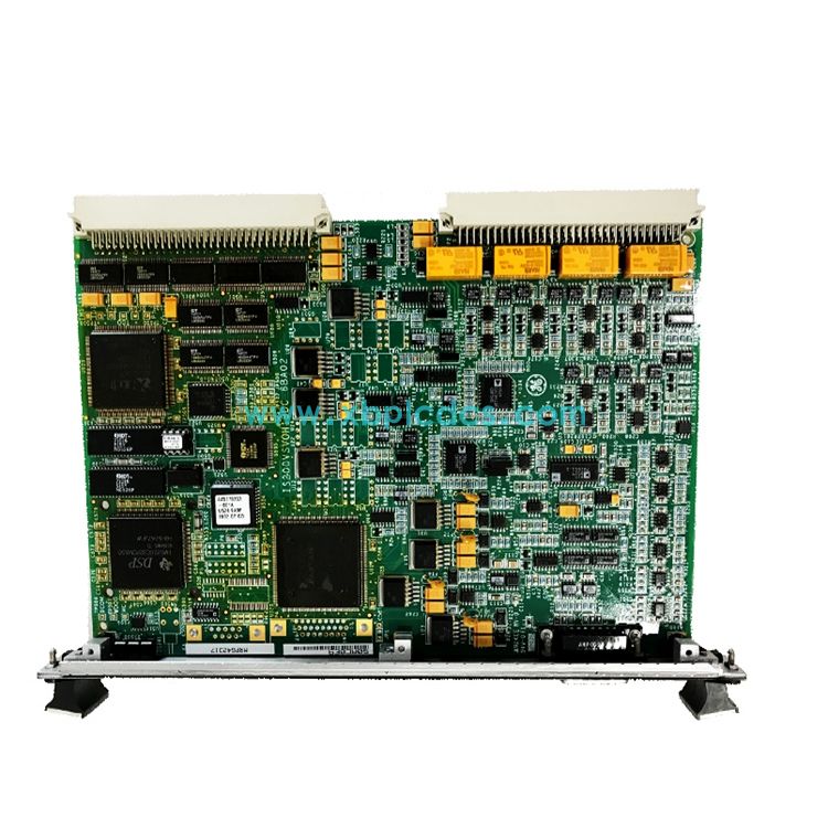
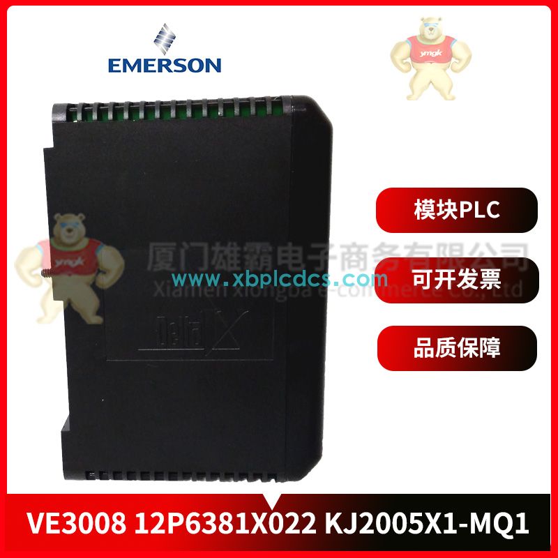
VE3008 Controller EMERSON

First, the question raised
Programmable controller technology is mainly applied in the automation control engineering, how to use the previous knowledge points synthetically, according to the actual engineering requirements reasonable combination of control system, this paper introduces the general method of composing programmable controller control system.
Two, programmable controller control system design of the basic steps
1. The main content of system design
(1) Formulate the technical conditions for the design of the control system. Technical conditions are generally determined in the form of a design assignment, which is the basis of the entire design;
(2) Select the electric transmission form and the actuator such as motor and solenoid valve;
(3) Select the type of PLC;
(4) Prepare PLC input/output distribution table or draw input/output terminal wiring diagram;
(5) Write software specifications according to the requirements of system design, and then use the corresponding programming language (commonly used ladder diagram) for programming;
(6) Understand and follow user cognitive psychology, attach importance to the design of human-machine interface, and enhance the friendly relationship between human and machine;
(7) Design operation table, electric cabinet and non-standard electrical components;
(8) Prepare the design specification and operation specification;
According to the specific task, the above content can be adjusted.
2. Basic steps of system design
(1) In-depth understanding and analysis of the process conditions and control requirements of the controlled object
A. A controlled object is a controlled machine, electrical equipment, production line or production process.
B. Control requirements mainly refer to the basic mode of control, the actions to be completed, the composition of automatic working cycles, necessary protection and interlocking, etc. For the complex control system, the control task can be divided into several independent parts, which can simplify the complex and is conducive to programming and debugging.
(2) Determine the I/O device
According to the functional requirements of the controlled object to the PLC control system, determine the user input and output equipment required by the system. The commonly used input equipment includes button, selector switch, travel switch, sensor, etc., and the commonly used output equipment includes relay, contactor, indicator light, solenoid valve, etc.
(3) Select the appropriate PLC type
According to the determined user I/O equipment, statistics required input signal and output signal points, select the appropriate PLC type, including model selection, capacity selection, I/O module selection, power module selection, etc.
(4) Allocate I/O points
Allocate the input and output points of PLC, prepare the input/output distribution table or draw the input/output terminal wiring diagram. Then nine can carry out PLC program design, at the same time can carry out control cabinet or operation table design and site construction.
(5) Design the application system ladder diagram program
According to the work function chart or state flow chart design ladder diagram is programming. This step is the most core work of the whole application system design, but also a more difficult step, to design the ladder diagram, first of all, we should be very familiar with the control requirements, but also have a certain practical experience in electrical design.
(6) Input the program into PLC
When using a simple programmer to input a program into a PLC, you need to first convert the ladder diagram into an instruction mnemonic for input. When the auxiliary programming software of the programmable controller is used to program on the computer, the program can be downloaded to the PLC through the connecting cable of the upper and lower machine.
(7) Software test
After the program is entered into PLC, it should be tested first. Because in the process of programming, there will inevitably be some omissions. Therefore, before the PLC is connected to the field equipment, it is necessary to carry out software testing, in order to eliminate the errors in the program, but also to lay a good foundation for the overall debugging, shorten the overall debugging cycle.
(8) Overall debugging of the application system
In the PLC hardware and software design and control cabinet and site construction is completed, you can carry out online debugging of the whole system, if the control system is composed of several parts, it should first make local debugging, and then the overall debugging; If the control program has more steps, it can be segmented debugging first, and then connected to the general tune. Troubleshoot the problems discovered during debugging until the debugging is successful.
(9) Prepare technical documents
System technical documents include instruction manual, electrical schematic diagram, electrical layout diagram, electrical component list, PLC ladder diagram.
3. PLC hardware system design
1. PLC model selection
Before making the decision of the system control scheme, it is necessary to understand the control requirements of the controlled object in detail, so as to decide whether to choose PLC for control.
When the logic relationship of the control system is complicated (requiring a large number of intermediate relays, time relays, counters, etc.), the process flow and product modification are frequent, the data processing and information management are required (including data calculation, simulation control, PID adjustment, etc.), the system requires high reliability and stability, and the factory automation networking is ready to be realized, etc. It is necessary to use PLC control.
At present, many manufacturers at home and abroad provide a variety of series of PLC products with different functions, so that users are dazzled and confused. Therefore, the comprehensive balance of advantages and disadvantages, reasonable selection of models to achieve the purpose of economic and practical. General selection of models to meet the needs of the system function for the purpose of not blindly greedy, so as not to cause the waste of investment and equipment resources. The choice of models can be considered from the following aspects.
(1) The selection of input/output points
Blind choice points more models will cause a certain waste.
To make clear in addition to the control system of I/O total points, and then according to the actual total points required 15 ~ 20% reserve amount (for the transformation of the system to leave room) to determine the number of PLC points required.
In addition, it should be noted that some modules with high density input points have limits on the number of input points connected at the same time. Generally, the input points connected at the same time should not exceed 60% of the total input points; PLC each output point driving capacity (A/ point) is also limited, some PLC each point output current size also varies with the load voltage added; Generally, the allowable output current of PLC decreases with the increase of ambient temperature. These problems should be considered in the selection.
PLC output point can be divided into common point type, grouping type and isolation type several connection. Isolated group of output points can be used between different voltage types and voltage levels, but the PLC average price per point is higher. If there is no need for isolation between the output signals, the PLC of the first two output modes should be selected.
(2) The selection of storage capacity
Only rough estimates of user storage capacity can be made. In the system of switching quantity control only, the total number of input points multiplied by 10 words/point + the total number of output points multiplied by 5 words/point can be estimated; Counter/timer according to (3 ~ 5) words/estimation; Calculation processing according to (5 ~ 10) word/quantity estimation; In the system with analog input/output, it can be estimated by the memory capacity of about (80 ~ 100) words per analog input/(or output). When there is communication processing, the number of more than 200 words per interface is roughly estimated. Finally, the margin is generally 50 ~ 100 % of the estimated capacity. For inexperienced designers, the choice of capacity should be more generous.
(3) The selection of I/O response time
The I/O response time of PLC includes input circuit delay, output circuit delay and time delay caused by scanning mode (generally in 2 ~ 3 scanning cycles). For the system of switching quantity control, PLC and I/O response time can generally meet the requirements of practical engineering, but do not need to consider the I/O response problem. However, this problem should be considered for the analog control system, especially the closed-loop system.
(4) Select the type according to the characteristics of the output load
Different load to PLC output mode has corresponding requirements. For example, for inductive loads that are frequently on and off, the transistor or thyristor output type should be selected rather than the relay output type. But the relay output type PLC has many advantages, such as small turn-on voltage drop, isolation effect, relatively cheap price, withstand instantaneous overvoltage and overcurrent ability is strong, its load voltage flexible (AC, DC) and a wide range of voltage levels. So infrequent action of AC, DC load can choose relay output type PLC.
(5) The choice of online and offline programming
Offline programming indicates that the host and the programmer share a CPU, through the programming way to select the switch to select PLC programming, monitoring and running state. In programming state, the CPU serves only the programmer and does not control the field. This is the case with dedicated programmer programming. Online programming refers to the host and the programmer each has a CPU, the host CPU to complete the control of the site, at the end of each scan cycle and the programmer communication, the programmer to the modified program to the host, the next scan cycle host will be according to the new program to control the site. Computer aided programming can realize both off-line programming and online programming. Online programming requires the purchase of a computer and the configuration of programming software. The choice of programming method should be based on need.
(6) Selection according to whether networking communication
If the PLC controlled system needs to be connected to the factory automation network, then the PLC needs to have the function of communication networking, that is, the PLC should have the interface to connect to other PLCS, the upper computer and the CRT. Large and medium machines have communication function, and most of the minicomputers have communication function.
(7) The selection of PLC structure form
With the same function and the same I/O point data, the integral is cheaper than the modular. But the modular has the advantages of flexible functional expansion, convenient maintenance (change module), easy to judge the fault, according to the actual need to choose the structure of PLC.
2. Assign input/output points
Generally the input point and the input signal, the output point and the output control are one-to-one correspondence.
After allocation, each input signal and output signal are allocated according to the channel and contact number configured by the system, that is, they are numbered.
In individual cases, there are also two signals with one input point, so the line should be connected according to a logical relationship before accessing the input point (such as two contacts in series or parallel), and then connected to the input point.
(1) Determine the I/O channel range
Different types of PLC, the range of its input/output channel is not the same, should be based on the selected PLC model, consult the corresponding programming manual, must not "wear." You must refer to the relevant operation manual.
(2) Part auxiliary relay
Internal auxiliary relays are not output to the outside world and cannot be directly connected to external devices. Instead, they are used for data storage or data processing when controlling other relays, timers/counters.
In terms of function, the internal auxiliary relay is equivalent to the intermediate relay in the traditional electric control cabinet.
The input/output relay area of the unallocated module and the link relay area when the 1:1 link is not used can be used as the internal auxiliary relay. According to the needs of program design, the internal auxiliary relays of PLC should be arranged reasonably. The purpose of each internal auxiliary relays in the program should be listed in detail in the design specification to avoid repeated use. Refer to the relevant operation manual.
(3) Allocate timer/counter
The number of timers/counters for PLC is shown separately in the relevant operation manual.
7.3 Design method and procedure of PLC software system
7.3.1 Method of PLC software system design
After understanding the PLC program structure, it is necessary to specifically prepare the program. There are many methods to compile PLC control program, here mainly introduces several typical programming methods.