Featured
Contact Us
Contact: YMGK Industrial Control
Phone: +86 18059884790
E-mail: plc66@qq.com
Add: whatsapp+86 18059884790
- Warehouse: Spot
- Warranty: 365 days
- Quality: Original module
- Condition: New / Used
- Shipping method: Courier delivery
- Contact person: Linda
- Contact number: +86 18059884790
- WeChat:18059884790
- E-mail: plc66@qq.com
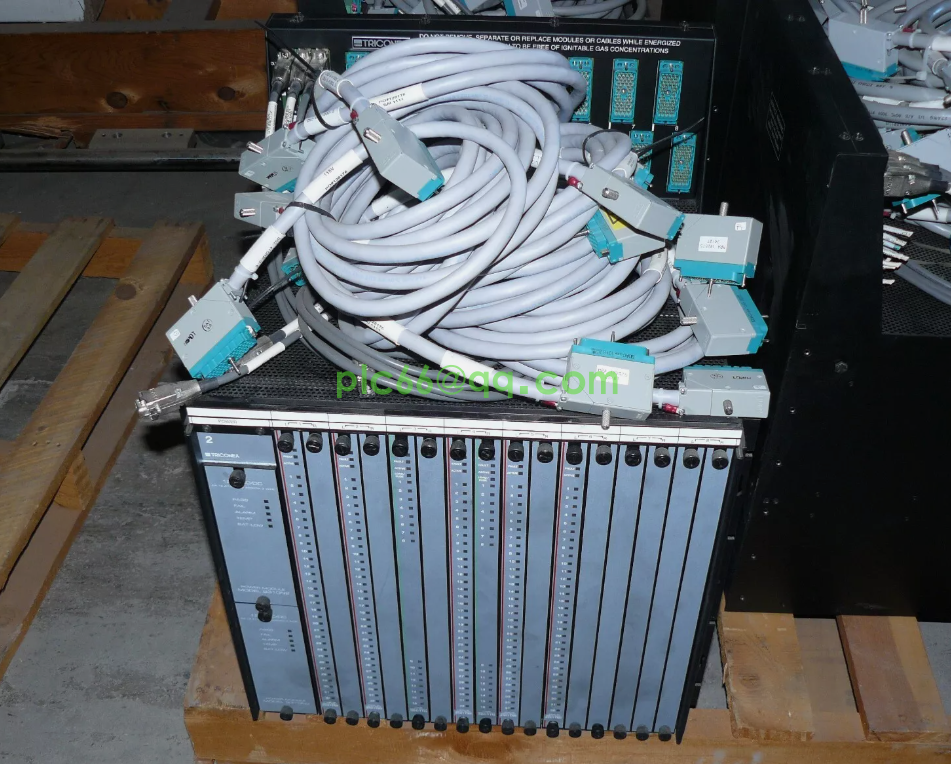
LPA302P-1 HITACHI controller module
LPA302P-1 HITACHI controller module
LPA302P-1 HITACHI controller module

The small and medium-sized rolling production line of Laigang was put into operation in 1997, mainly producing round steel, spring flat steel, channel steel and rebar steel. The PLC control system of this production line is provided by ABB company, and its automatic control system adopts ABBMasterpiece200/1 PLC control system, realizing the automatic control of 18 rolling mills, cold bed, cold shear and palletizing machine. The basic automation system uses ABB's RMC200 rolling control system, which is an open distributed control system consisting of an MP200/1 process station and an AS520 operator station. The process station is composed of a CPU rack and an I/O rack. The CPU rack is equipped with CPU template DSPC172, memory template DSMB176 and 32-channel DI/DO template. It is connected to the MasterBus300 bus through the communication template DSCS140 to communicate with other process stations. I/O rack by the bus expansion module DSBC172 bus expansion.
The operator station adopts HP-UNIX workstation and connects to the redundant interface of MasterBus300 through the real-time accelerator board, through which the operator can directly monitor the field equipment. The main functions include 1) start and stop of rolling production equipment, 2) equipment data setting and real-time monitoring, and 3) display and print of event and alarm list. The main screen of the system includes starting screen, setting screen, maintenance screen, event screen and alarm screen.
2. The basic principle of PLC fault diagnosis of rolling production equipment
The fault signal of steel rolling equipment is divided into digital quantity and analog quantity. PLC adopts different methods to diagnose the fault corresponding to these two signals.
2.1 Fault diagnosis based on digital quantity signal
The recognition of digital signal by PLC is completed by its digital input module. When PLC controls steel rolling production equipment, digital sensors such as pressure, temperature, level, stroke number and operation button in the equipment are connected with the input terminal of PLC. Each input terminal is allocated with a "bit" in the data area of PLC, and each "bit" is an address in the memory. Reading the status value of PLC input bit can be used as the basis to identify the digital quantity fault signal. The process of diagnosis of digital fault, in essence, is the PLC normal input bit state value and the corresponding input bit actual state value compared process. If the two comparison results are consistent, it indicates that the equipment is in normal working condition; if they are inconsistent, it indicates that the equipment part corresponding to the input bit is in fault working condition. This is the basic principle of PLC diagnosis based on digital signal fault. This diagnosis method is accurate in fault location and can be used for real-time online diagnosis. Through the graphic function block programming of PLC, the fault diagnosis can be integrated into the process control to achieve the purpose of protecting the rolling equipment.
2.2 Fault diagnosis based on analog signal
PLC to analog signal recognition is through PLC analog input and output module to complete. Analog input/output module adopts A/D conversion principle, the input end receives the analog signal from the sensor or transmitter, and the output end outputs the analog signal acting on the PLC control object. PLC diagnosis of analog fault process, the essence is in the corresponding A/D channel read the analog signal of the actual value of the system allowed limit value compared with the process. If the result of comparison is that the actual value is far from the limit value, it indicates that the monitored part corresponding to the rolling production equipment is in normal state, and if the actual value is close to or reaches the limit value, it is abnormal state. The limit value for judging whether the fault occurs or not is determined according to the corresponding parameter variation range of the actual system. The limit value can be precisely set by using the analog quantity setting switch on PLC.
When the actual value of the analog quantity reaches the set value of the analog quantity setting switch, PLC can also start the output bit on the switch quantity module according to a certain logical relationship, or initiate communication from the PLC communication port, so as to output the result of fault diagnosis, and thus realize the control of rolling production equipment.
2.3 Fault Diagnosis based on interrupt mode
The interrupt mode of PLC is as follows:
(1) Input interruption;
(2) Interval timer is interrupted;
(3) High-speed counter interruption. Among them, the input interrupt is especially suitable for the fault diagnosis of rolling production equipment. It corresponds to the hard interrupt of the industrial operation station, which belongs to the external interrupt, but the input interrupt of PLC can be shielded by the external instruction of PLC. The fault signal of steel rolling production equipment is taken as the input interrupt source of PLC. Once the fault signal occurs, the CPU will respond immediately, stop the program being executed, and turn to the interrupt subroutine to deal with the fault conveniently. It and the direct use of the internal logic of PLC to complete the fault diagnosis difference lies in: using the input interrupt to deal with the fault, can stop the execution process of PLC main program, and directly use the input and internal logic of PLC to deal with the fault, the main program of PLC is still in the running state. Therefore, the proper fault diagnosis method should be selected according to the influence of the fault on the rolling production equipment. The input interrupt mode of PLC is especially useful for the treatment of the sudden failure with serious consequences. The function of 3PLC in fault diagnosis system
The fault diagnosis system is a typical man-machine system. According to the result of information flow and function division in the system [1], the fault diagnosis system based on the intelligent operation station is shown in Figure 2.
The input module of the system should receive the fault detection signal, control instruction and expert knowledge of the rolling production equipment. The processing module requires automatic feature parameter extraction and control instruction code conversion. The organization and presentation of expert knowledge is done in collaboration with domain experts and systems experts. The control module is the core of the fault diagnosis system. According to the control instruction, it uses the expert knowledge to identify the fault characteristics and the fault causes. The more complete the function of the control module, the more intelligent the fault diagnosis system is. The output module gives the result of fault location, prediction and interpretation through the sound and light alarm device and the man-machine interface. Among them, the man-machine interface can also provide the technical route of troubleshooting. To realize the automatic flow of the information source from the input module to the output module and reduce the human intervention is the requirement of the rolling production equipment to its fault diagnosis system. PLC fault diagnosis system is helpful to realize the automation of fault diagnosis process.
4. Use PLC and operation station to realize intelligent diagnosis
Intelligent fault diagnosis of rolling production equipment can make full use of expert knowledge and improve diagnosis efficiency, which is an important direction of fault diagnosis technology development. Because the current PLC products do not have the function of automatic acquisition and storage of expert knowledge, the programming language can not complete the control layer of the calculation and reasoning function, therefore, the intelligent degree of fault diagnosis system simply using PLC is quite limited. Therefore, using network technology and communication technology, PLC and operation station can be connected into a network to complement each other's strengths and make up the hardware system of fault diagnosis. PLC adopts parallel distributed structure, for the use of the next machine, the operation station as the upper computer, can complete the PLC program under the installation, the implementation of multiple PLC management, the complex data operation, the establishment of the database, the storage of expert knowledge, the input and output equipment can be used as the diagnostic process of human-computer interaction. PLC and the operation station are connected into A whole through two ways: one is through the communication port of PLC and the communication port of the operation station for connection, the other is through the input and output terminals of PLC and the switching plate and A/D board on the operation station for connection. Among them, PLC through the communication port to the host computer as many as 2 or more fault signals, the host computer through coding identification, and through the PLC output terminal to the host computer fault signal, the host computer through the switch quantity board input terminal address to identify. The PLC input terminal can accept the control signal or fault signal from the upper computer. PLC and operation station in the network play different roles in the fault diagnosis system.
In general, in the process of fault diagnosis, the complicated logic judgment, the detection of the switch fault signal and the protection of the equipment under the condition of serious fault can be handed over to PLC, and the complex numerical calculation and human-computer interaction can be completed in the upper computer.
5 Application Effect
The whole workshop automation system is a two-stage control system, namely equipment control level and information management level. The first-stage equipment control system is RMC200 rolling line control system using ABBMasterPiece system. It consists of 10 ABBMasterPiece200/1 process stations, 3 MasterPiece90 process stations, 3 AdvantStation500 series operating stations, 1 VT340 monitoring station and 2 MasterAid220 programming stations. The network communication between the process stations is MasterBus300(MB300 for short), which communicates with the secondary information management level through the process station of the heating furnace. Each MP200/1 process station is connected to the MB300 network through a DSCS140 communication board, through which data is exchanged. The address switch can be set on the communication board to determine the location of the node on the network. For the communication between MP200/1 and the baling machine MP90, the communication board DSCS131 in the RMC7 system is connected to the MODEM. The baling machine is also equipped with a MODEM and a communication board DSCS131 respectively to realize remote communication by the MODEM. In the MP200/1 system of the heating furnace RMC1, DSCS150 board communicates with the server of the secondary computer system IBMNetifinity5000, and they exchange data through GCOM network. The following takes RMC2 as an example to introduce the realization of intelligent fault diagnosis of rolling production equipment.
RMC2 actually includes three sets of PLCS :RMC2, RMC52, RMC62, The main control functions of RMC2 include: setting and storage of rolling schedule, control of pre-furnace charging equipment (including hot feeding and cold billet loading), measurement and weighing of pre-furnace billet, control of heating furnace outlet equipment, main drive control of roughing mill, micro-tension control of roughing mill, and control of 6# scissors. The main control functions of RMC52 are: control of rolling mill (including speed cascade, speed setting, tracking), rolling line simulation test, lofter scanner control of rolling mill; The main control functions of RMC62 are: finish mill control (including speed cascade, speed setting, tracking), finish mill group lopper scanner control. RMC2, RMC52 and RMC62 not only need to complete their own control functions independently, but also interlock and interlock each other. If there is any error in the control of the lopper scanner of the middle rolling unit, the rolling steel control system cannot operate normally, the 6# scissors will be broken immediately to prevent the rolling line from piling steel, and the heating furnace will stop producing steel until the fault is removed. The designed fault diagnosis system can complete the following functions:
(1) Before the test process starts, run the fault diagnosis system to check whether the rolling production control system is in good condition. For the switching quantity, this process is the upper computer through the communication port to read the PLC input bit state value and compare with its normal state value process; For the analog quantity, this process can be judged by reading the status value of the switch started by the analog quantity, or by comparing the analog quantity read from other stations with its corresponding limit value. If a fault is found in the measurement and control system, it should be dealt with in time (the display screen of the upper computer gives the alarm of the specific fault location). The rolling performance test can only be performed when the diagnosis results are in good condition.
(2) If the test results find unqualified equipment, the fault diagnosis system should be re-run.
(3) If there is a serious fault in the measurement and control system during the test process, the PLC transmits the fault signal through the communication port or the input and output board of the upper computer, so that the measurement and control system exits the test process, and the screen gives the fault diagnosis results and troubleshooting suggestions.
6 Closing Remarks
PLC can provide powerful technical support for the fault diagnosis of steel rolling production equipment. In the design of fault diagnosis system, according to the functional requirements of the diagnosis system, choose the appropriate PLC, can enrich and improve the function of the diagnosis system. With the successful development of PLC new products, it will have a broader application prospect in the field of fault diagnosis.
www.xbplcdcs.com