
Featured

Contact Us
Contact: YMGK Industrial Control
Phone: +86 18059884790
E-mail: plc66@qq.com
Add: whatsapp+86 18059884790
- Warehouse: Spot
- Warranty: 365 days
- Quality: Original module
- Condition: New / Used
- Shipping method: Courier delivery
- Contact person: Linda
- Contact number: +86 18059884790
- WeChat:18059884790
- E-mail: plc66@qq.com
Product Description
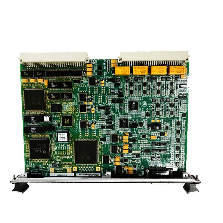
The IS200AEAAH1CPR1 is a GE PCB designed as a component for the Mark VI series. The Mark VI is part of the Speedtronic series for gas/steam heavy-duty turbine management. This series has been in use since GE released the first of the Speedtronic systems (Mark I) in the late 1960s. The Mark VI used the most advanced technology available at the time of its release and includes a Windows-based PC operator interface. The Mark VI is also designed around GE proprietary software like CIMPLICITY graphics and the GE Control System Toolbox, which is used for maintenance.
The IS200AEAAH1CPR1 has three terminal strips. These are placed parallel to each other on the surface of the board. Each strip has twelve positions. The board has a female jack connector located along its right edge. This is a right-angled connector. There is also a 2-position female connector (J4) located along the top edge. The board has a three-pin vertical male pin connector located along the top edge. This is labeled P18.
The IS200AEAAH1CPR1 has sixteen vertical metal connectors. Eight of these are located along the left edge of the board. These are labeled P1 through P8. P10 through P17 are located in two boxes on the top edge of the board, with the even connectors located in one box and the odd in another.
The IS200AEAAH1CPR1 has eight relays. These are marked K1 through K8. They are located on the board in two blocks of four. Two heat sinks are located next to these components. Directly below the heatsinks there are three large wire wound resistors. The board has an additional 200+ resistors of other types. It also has various capacitors and diodes, as well as over forty integrated circuits.
We suggest following installation guidelines as written in manuals or data sheets supplied by the original manufacturer.