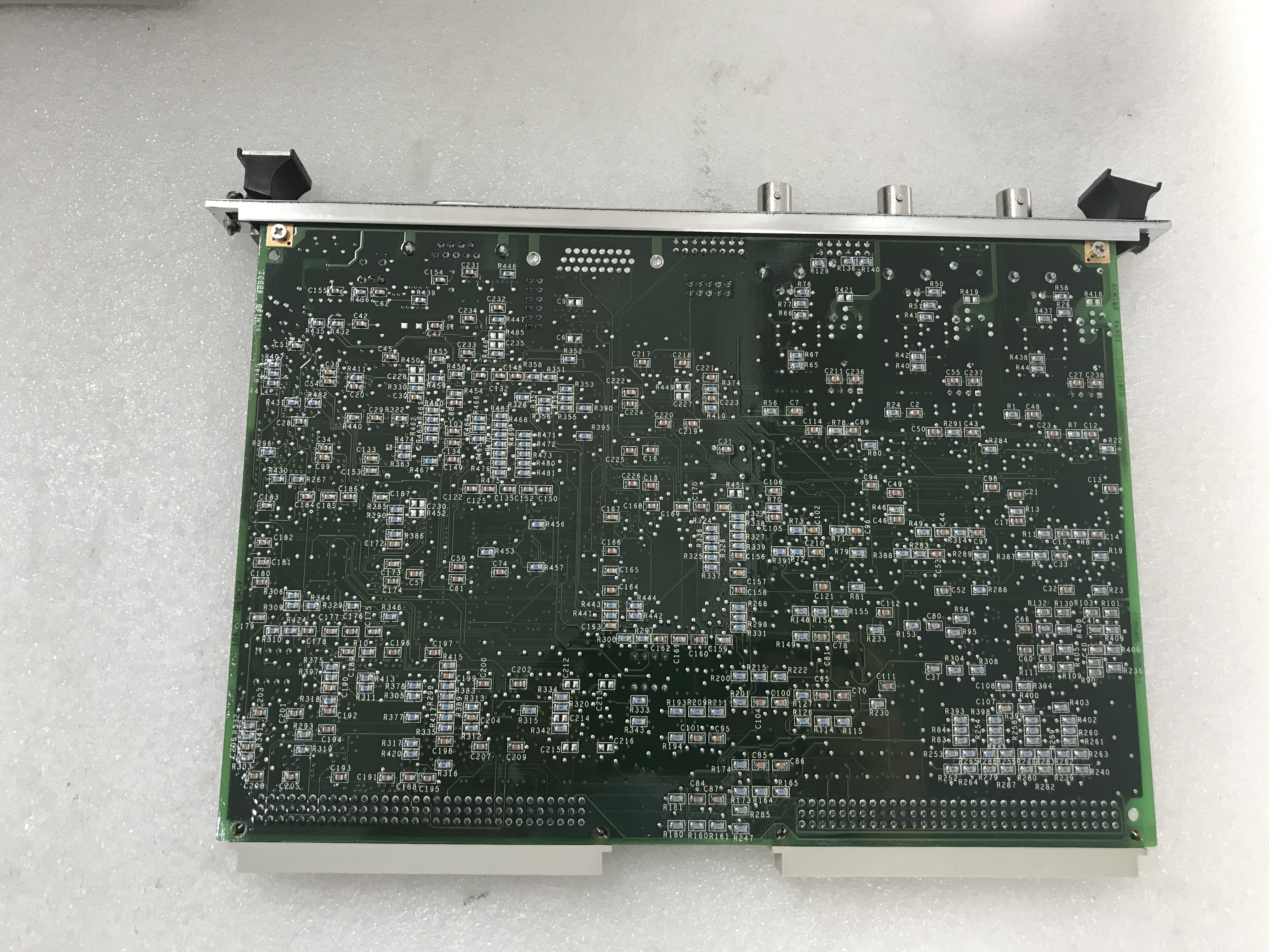
Product Description
The GE Digital Contact Terminal Board DS200DTBAG1 features two terminal blocks that each connect a maximum of 95 wires. DS200DTBAG1 also features 5 jumpers and two 2-pin connectors. After you disconnect the drive from electric power you can begin to replace the drive. Due to the 190 signal wires connected to the terminal blocks you must document where the wires are connected. To make it easy the terminals have a letter and number designation and you can attach the designation information on the wire. If you have a large number of wires attached to the terminal, allow plenty of time to identify the terminals on the wire. Do the same with the other connectors.
The jumpers are set to define the configuration of the board and so to ensure the replacement board works the same as the old board, you have to set the jumpers in the same positions. Some of the jumpers are only used at the factory for testing purposes and cannot be moved because the configuration in the alternate position is not supported. Regardless, record the position of all five jumpers on the old board using the designation printed on the board which is prefixed with JP. Like, for example JP1, JP2, and JP3.
Setup up the wrist strap by connecting one end to a metal surface that is paint free and wrap the other end around your wrist. Open the protective bag and slid out the board and rest the board on top of the bag.