Linda Phone:+86 18059884790      中文版
Product
Product

Contact Us

Contact: YMGK Industrial Control

Phone: +86 18059884790

E-mail: plc66@qq.com

Add: No. 9, 14th Floor, Building 42, Hongshan Lake Road, North Street, Xixiu District, Anshun City, Guizhou Province, China

GE通用
DS200DTBBG1ABB
  • Warehouse: Spot
  • Warranty: 365 days
  • Quality: Original module
  • Condition: New / Used
  • Shipping method: Courier delivery

  • Contact person: Linda
  • Contact number: +86 18059884790
  • WeChat:18059884790
  • E-mail: plc66@qq.com

Product Description

DS200DTBBG1ABB Technical Specifications

ManufacturerGE General Electric
SeriesMark V
Part NumberDS200DTBBG1ABB
Product TypeContact Input Expansion Termination Module

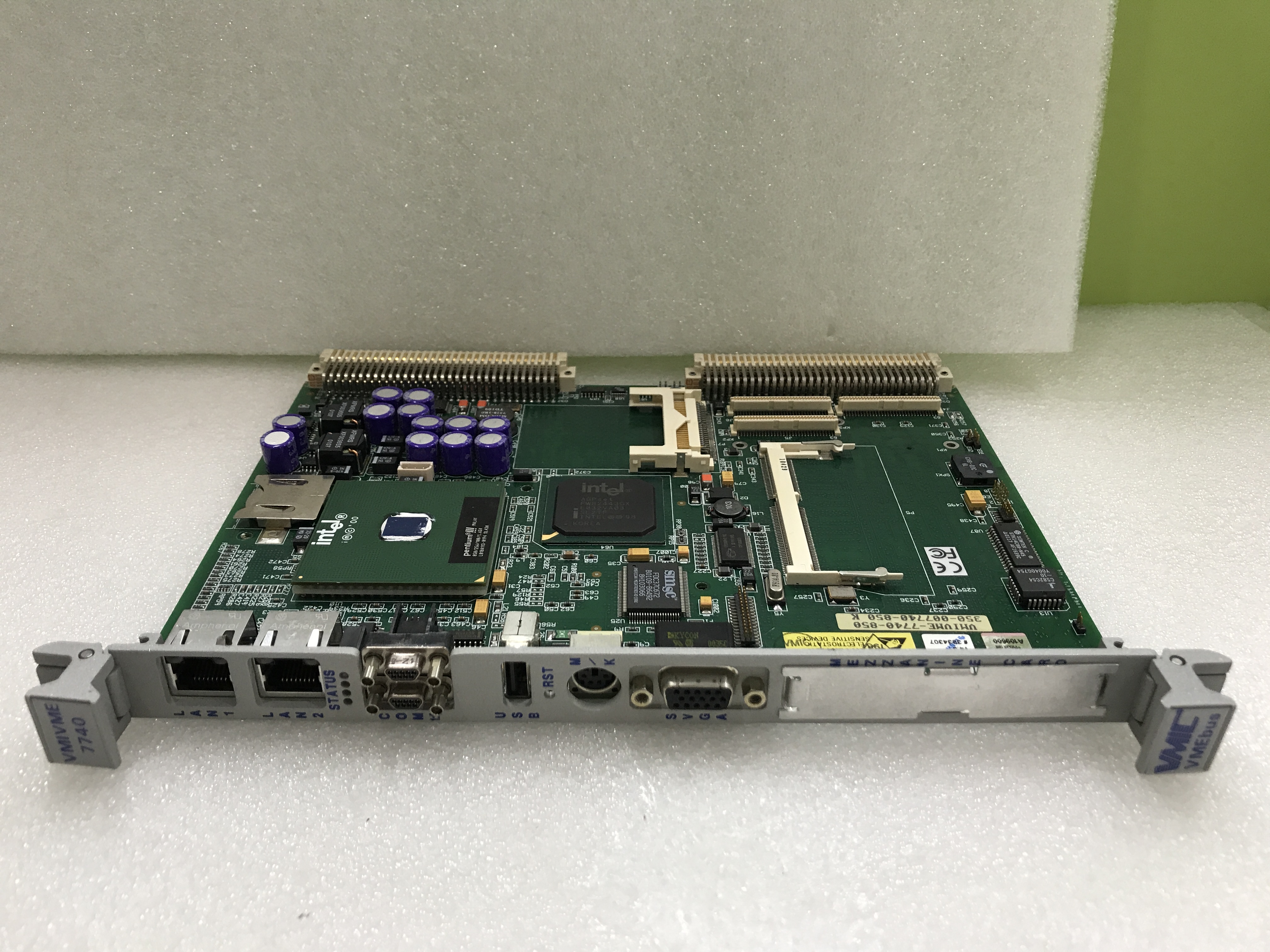
VME7740-841.蒋娜.202103180902236 (4).png

Product Description

The GE Terminal Digital Connector Board DS200DTBBGIABB features 2 terminal blocks with terminals for 95 signal wires in each. It also contains 3 50-pin connectors. The IDs for the 40-pin connectors are JFF, JFG, and JFH. It also is populated with bayonet connectors and 5 jumpers.

The board is 3 inches in height and 11.5 inches in length. It has 1 hole in each corner for the installer to attach the board to the board rack in the interior of the drive. The drive has multiple positions that can accept the installation of the board. However, it is best practice to install the board in the same position as the old board it is replacing. This is because of the large number of signal wires and ribbon cables attached to it. Cable routing is very important. If the cables are not routed properly interference can result and also the cooling of the drive interior can be negatively affected. The drive interior has many power cables and signal wires and ribbon cables. The power cables if routed too near the signal wires can interfere with the signals. This might result in inaccurate signals being transmitted and received by the board. The solution is to route the power cables as far as possible from the signal wires.

The other problem that can result from improper cable routing is reduced air flow within the drive. This can occur if bundles of cables block the flow of air in front of air vents or around components that generate heat.

Frequently Asked Questions about DS200DTBBG1ABB

What is the input voltage on DS200DTBBG1ABB?
DS200DTBBG1ABB has an input voltage range between 24 VDC and 125 VDC. When DS200DTBBG1ABB uses 24 VDC inputs, DS200DTBBG1ABB requires an external power supply.
What digital inputs is DS200DTBBG1ABB used with?
DS200DTBBG1ABB is the termination for digital contact inputs 47-96.
Where is DS200DTBBG1ABB located?
DS200DTBBG1ABB is located in the < Q11 > and < Q51 > cores.
What are the connectors on DS200DTBBG1ABB?
DS200DTBBG1ABB has 3 connectors. DS200DTBBG1ABB's JRR connector writes the contact input signals to the TCDA board. Connector JY on DS200DTBBG1ABB receives the 125 VDC power from the DTBA board. And connector JRS/T on DS200DTBBG1ABB is typically not used though it is still one of DS200DTBBG1ABB's connectors.


Related recommendations