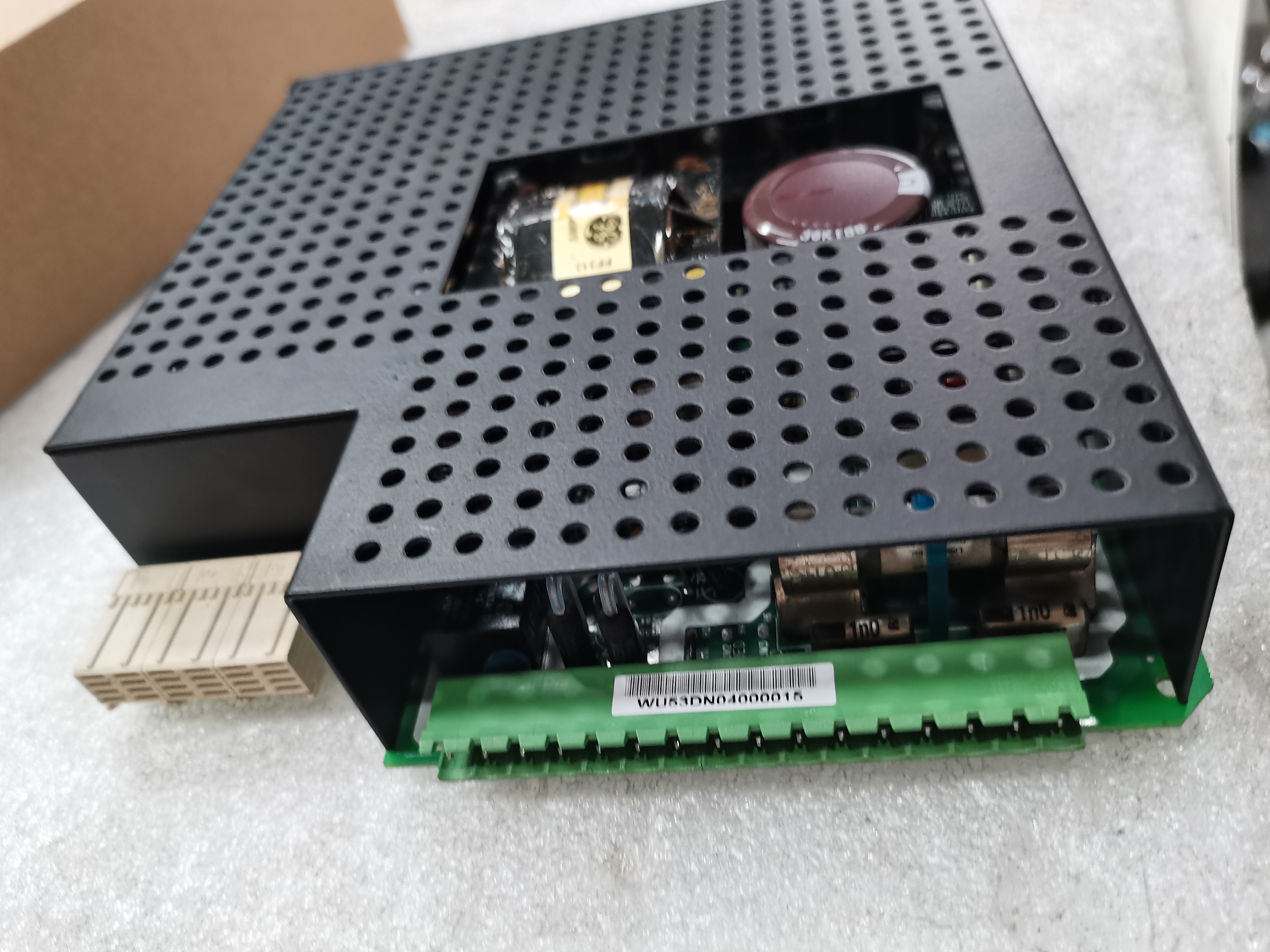
The GE Connector Relay Terminal Board DS200DTBCGIA features 2 terminal blocks with terminals for 110 signal wires in each. It also contains 2 3-wire bayonet connectors and 1 2-wire bayonet connector and 10 jumpers.
The board is 3 inches in height and 11.5 inches in length. Spaces are available inside the drive for mounting the board. Because the board can have 220 signal wires attached to it, it is important that you mount it where the signal wires can be routed properly. The signal wires can not be routed near power cables due to the risk of interference. The power cables are considered noisy which means they radiate signal noise that can interfere with the accuracy of the signals received by the board. They also interfere with the signals received by the board. Sometimes shielded wires can be used to block the interference. However, the best solution is to route the power cables separately from the signal wires. If they must be routed together, it is best to limit the length of the run they are bundled together. The more current a power cable carries the further away the power cable and signal cables should be routed from each other.
Route the signal wires so that they do not interfere with the air flow inside the drive. The drive is designed so that cool air enters the drive at the bottom of the drive through air vents. The air flows over the heated components and carries away the heat through vents at the top of the drive.
If fiber optic cables are routed inside the drive, the power cables can be routed together with the fiber optic cables. That is because fiber optic cable are immune from interference.
