DS200EXDEG1A Technical Specifications
| Manufacturer | GE General Electric |
| Series | Mark V |
| Part Number | DS200EXDEG1A |
| Product Type | DE-Excitation Control Board |


Contact: YMGK Industrial Control
Phone: +86 18059884790
E-mail: plc66@qq.com
Add: fujian xiamen
")
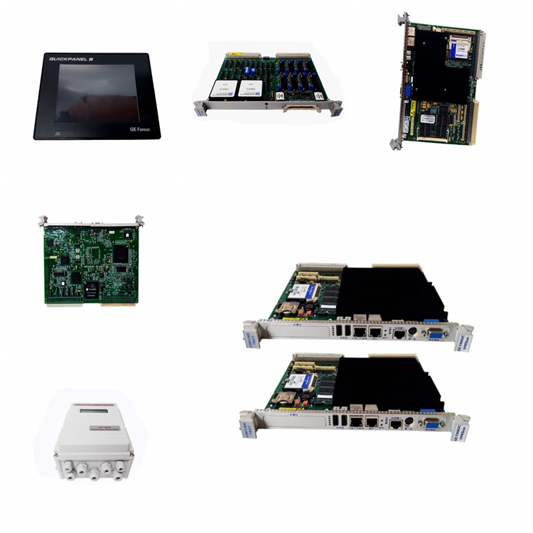
The GE Excitation Control Board DS200EXDEG1A features 2 34-pin connectors, 2 10-pin connectors, and 5 indicator LEDs. It is also populated with 8 capacitors, test points, and terminal connectors. During normal processing the capacitors store high-voltage current and when signalled, a circuit on the board releases the high voltage. The same circuits again begin the process of storing high-voltage current. During normal operation the operator is unaware of the cycle and is not exposed to safety concerns because of the capacitors.
However, when the board is being replaced, the servicer is potentially exposed to the high-voltage current. Best practice is to allow the high-voltage current in the capacitors to dissipate before touching the board. This only takes 30 seconds. In short, to avoid high-voltage current, wait 30 seconds before touching the board after removing external power.
The board has 5 OK LEDs that are visible to the operator. They lit when the board passes all diagnostic checks performed at startup and remain on if no errors are encountered. This gives the operator a quick means of monitoring the status of the board during normal processing.
The terminal connectors are used to connect jumper cables to achieve a particular processing outcome. The written documentation provides a description of the terminal connectors and the specific outcome that can be achieved by jumpering two terminal connectors together. The jumper cables have connectors that fit over the terminals.
Power is supplied to the board through the plug connector. When connected properly, the connector snaps into place. To remove the cable, hold the plug end and pull it out of the connector.
Tel:+86 18059884790
E-mail:plc66@qq.com
E-mail2:1033732479@qq.com
Address:fujian xiamen
WHATSAPP:+86 18059884790
YOUTUBE:KIMI-YMGK
SKYPE:
Copyright © Xiamen Xiongba E-Commerce Co., Ltd.