Contact Us
Contact: YMGK Industrial Control
Phone: +86 18059884790
E-mail: plc66@qq.com
Add: No. 9, 14th Floor, Building 42, Hongshan Lake Road, North Street, Xixiu District, Anshun City, Guizhou Province, China
- Warehouse: Spot
- Warranty: 365 days
- Quality: Original module
- Condition: New / Used
- Shipping method: Courier delivery
- Contact person: Linda
- Contact number: +86 18059884790
- WeChat:18059884790
- E-mail: plc66@qq.com
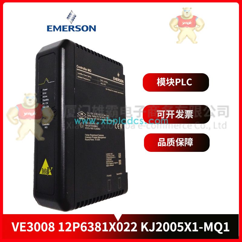
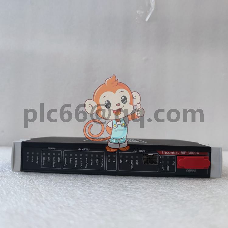
VE3006 EMERSON I/O module
Emerson Process Management, Fisher Rosemount Systems
Catalog Description: VE3006, Controller MD Plus, LocalBus Power Rating 5VDC, 1.4A Max., Ambient Temperature 0 to 60 degrees C
Alternate Part Numbers: KJ2003X1-BB1, KJ2003X1BB1, 12P3439X012 and 12P3439X032
Common Typographical Errors: VE3OO6

The composition of PLC in a manipulator control system is as follows:
1. Input unit
The input unit consists of 8 buttons, 8 switches and 16 connectors, which are respectively connected with 16 input points of PLC. Change the on/off state of these switches or press the button, you can input the required switch quantity to the host. 16 connectors can be external to other DC or switching input signals.
2. Output unit
The output unit consists of 24 diodes and 24 connectors, which are respectively connected with 24 output points of PLC. The state of the output point can be expressed if the LED is luminous, and the user can get the output information of the host. 24 output connectors can be connected to other devices that need to be controlled. The four ground ends of the output unit are drawn to the panel respectively, among which only C4 and 3V power supply share ground.
3. Power supply unit
The left side of the PLC host is equipped with an external 220V/AV power socket, which is used as the working power supply of PLC. Built-in transformer, output 3V power supply for diode use. In addition, 24VDC and 24GND of PLC have been led out to the panel for the working power supply of external input devices (such as sensors).
4. System procedures
System program is the basis of PLC work, using assembly language, in the PLC factory has been solidified in the ROM system program memory.
The system program is divided into system monitoring program and interpretation program.
The system monitoring program is used to monitor and control the work of PLC, such as diagnosing whether the PLC system works normally, controlling the work of the PLC modules, exchanging information with the place, according to the user's setting so that the PLC is in the preparation of the user program state or in the running of the user program state.
Interpreters are used to interpret user programs into programs that the microprocessor can execute. From the House of PLC.
5. User programs
User program, also known as the application program, is the user to complete a specific control task and the use of PLC programming language program. From the House of PLC.
The user program is input into the PLC user program memory through the programmer.
6. Programming languages
Programmable controller is through the program to control the system, so all kinds of models of PLC have their own programming language.
PLC programming language has a variety of, such as ladder diagram, statement table, logic function diagram, logic equation. The following describes the common ladder diagram and statement table programming languages.