Featured
Contact Us
Contact: YMGK Industrial Control
Phone: +86 18059884790
E-mail: plc66@qq.com
Add: whatsapp+86 18059884790
- Warehouse: Spot
- Warranty: 365 days
- Quality: Original module
- Condition: New / Used
- Shipping method: Courier delivery
- Contact person: Linda
- Contact number: +86 18059884790
- WeChat:18059884790
- E-mail: plc66@qq.com
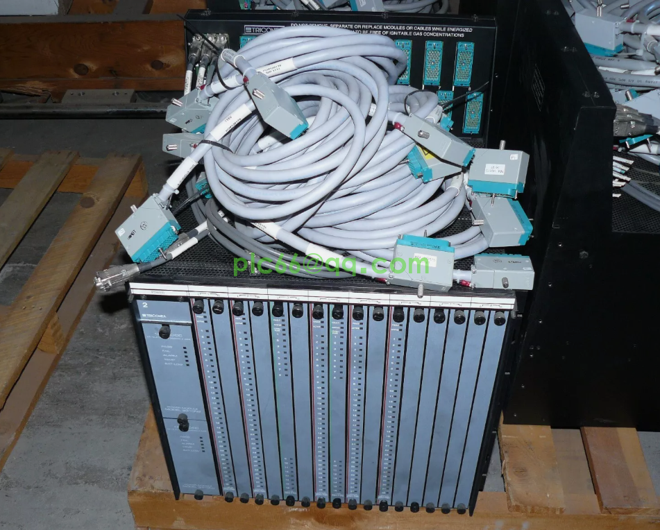
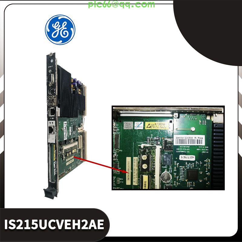
LPA245A HITACHI controller module
LPA245A HITACHI controller module
The input/output interface is the connection component between the PLC and the field I/O device or other external devices. Through the input interface, PLC reads the status or information of external devices (such as switches, buttons, sensors) into the CPU. Through the calculation and operation of the user program, the results are transmitted to the actuator (such as solenoid valve, relay, contactor, etc.) through the output interface.
In the input/output interface circuit, generally equipped with electronic transformation, optical coupler and resistance capacitance filtering circuit, in order to achieve the external field of various signals and the system internal unified signal matching and correct signal transmission, PLC is through this interface to achieve the signal level conversion. Light emitting diode (LED) is used to show whether a certain input terminal has signal input. When the system's I/O points are not enough, the PLC's I/O expansion interface can be used to expand the system.
(1) Input interface circuit
Various PLC input interface circuit structure is mostly the same, according to its interface to accept the external signal power supply divided into two types: DC input interface circuit, AC input interface circuit. Its function is to change the field switching signal into the PLC internal processing standard signal. The input interface circuit of PLC is shown in Figure 2.
In the input interface circuit, each input terminal can receive a discrete signal from the user's equipment, that is, the external input devices can be passive contacts, such as buttons, switches, profile switches, etc., or active devices, such as various sensors, proximity switches, photoelectric switches, etc. Under the condition that the capacity of the PLC internal power supply allows, the active input device can use the PLC output power supply (24V), otherwise it must be peripheral power supply.
In Figure (a) DC input interface circuit, when the input switch is closed, the photosensitive transistor receives the optical signal and sends the received signal to the internal status register. That is, when the field switch is closed, the corresponding input image register is "1", and the light emitting diode (LED) at the input end is on; When the field switch is off, the corresponding input image register is in the "0" state. The photoelectric coupler isolated the electrical connection between the input circuit and the PLC internal circuit, so that the external signal through the photoelectric coupling into the internal circuit can receive the standard signal.
Figure (b) In the AC input interface circuit, when the input switch is closed, the signal is sent to the PLC internal circuit through the bi-directional optocoupler for CPU processing, and the light emitting diode (LED) is lit at the same time.
(2) Output interface circuit
In order to adapt to different load needs, the output of various types of PLC has three types of interface circuit, namely relay output, transistor output, thyristor output. Its function is to convert the PLC internal standard signal into the on-off signal required by the actuator on site, and drive the load. Light emitting diode (LED) is used to show whether a certain output terminal has signal output.
Figure (a) In the relay output interface circuit, when the CPU sends the output signal to the output image area of PLC according to the operation of the user program, the output signal is sent to the latch through the internal bus. When the corresponding bit of the output latch is "1", the corresponding light-emitting diode (LED) is switched on and emits light. The coil of the relay is charged, and the contacts connect the load with the power supply, making the load obtain current. When the corresponding bit of the output latch is "0", the corresponding light emitting diode (LED) is not switched on, the coil is not charged, and the contact will cut off the load L and the power supply, so that the load will not get current.
Figure (b) transistor output interface circuit, when the corresponding bit of the output latch is "1", the corresponding transistor is switched on, the load and the power supply is connected, so that the load obtains current, light emitting diode (LED) on; When the corresponding output latch is "0", its corresponding transistor cut-off, the load and power supply partition, so that the load will not get current, light emitting diode (LED) is not switched on.
Figure (c) In the thyristor output interface circuit, when the corresponding bit of the output latch is "1", the corresponding optical coupler is switched on to connect the load and the power supply, so that the load obtains current and the light emitting diode (LED) emits light. When the corresponding bit of the output latch is "0", because the load power supply is zero, the corresponding optical coupler is cut off, the load and power supply is cut off, so that the load will not get current, light emitting diode (LED) is not switched on.
Among the above three types of output interface circuit, the relay output type is the most commonly used. It is suitable for AC and DC loads. It is characterized by strong load capacity, but slow operation frequency and corresponding speed. The transistor output type is suitable for DC load, which is characterized by high frequency of action, corresponding speed block, but with small load capacity. Thyristor output type is suitable for AC load, the corresponding speed is fast, and the load capacity is not strong.
In the output interface circ
uit, the external load is directly connected to the PLC output terminal, and the load power supply is equipped by the user according to the load requirements. In practical applications, when considering the external drive power supply, the type of the output device should be considered, and the output current of the PLC output terminal should not exceed its rating.
www.xbplcdcs.com