
Featured


Contact Us
Contact: YMGK Industrial Control
Phone: +86 18059884790
E-mail: plc66@qq.com
Add: whatsapp+86 18059884790
- Warehouse: Spot
- Warranty: 365 days
- Quality: Original module
- Condition: New / Used
- Shipping method: Courier delivery
- Contact person: Linda
- Contact number: +86 18059884790
- WeChat:18059884790
- E-mail: plc66@qq.com
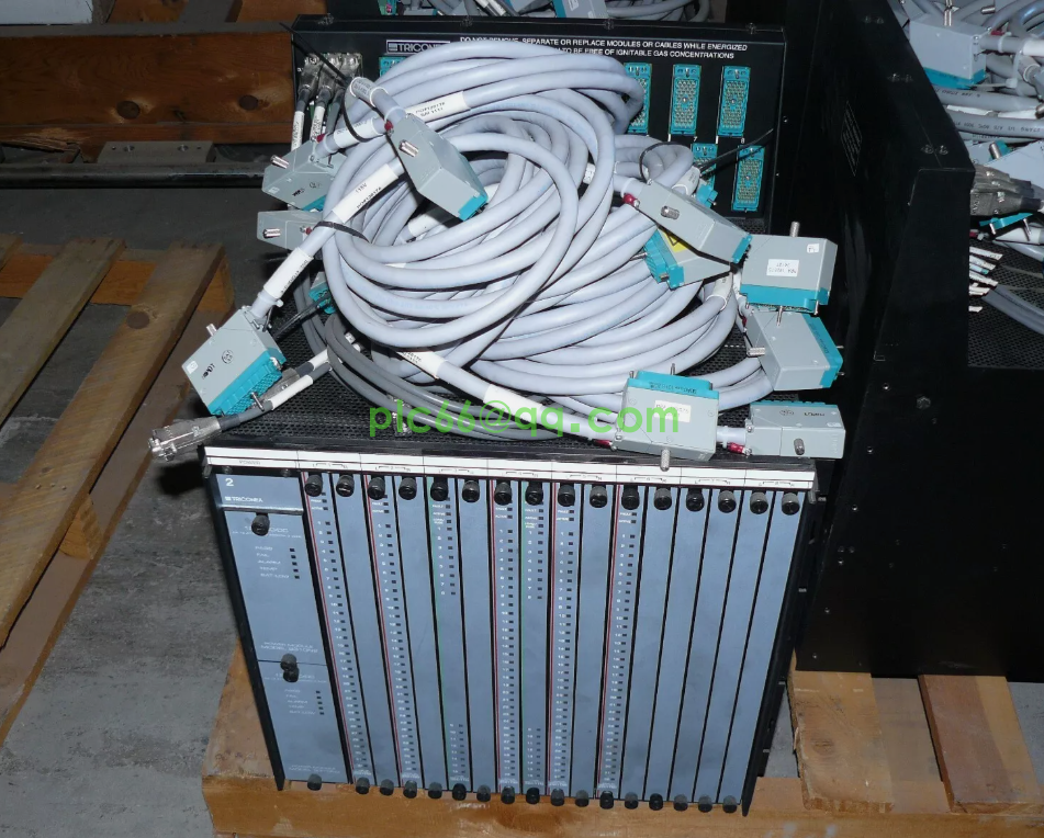
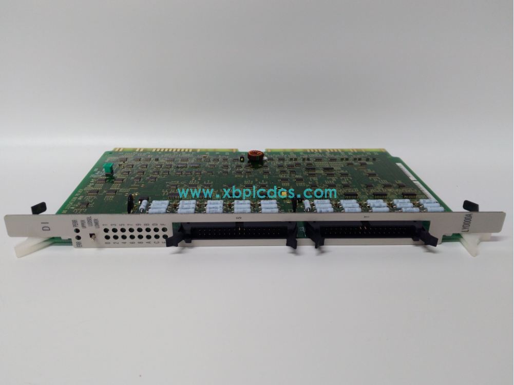
LPA220A HITACHI controller module
The water level measurement and control device is an important measurement and control equipment of hydropower plant, and the water level of upstream and downstream of hydropower plant is an important data of flood control safety. The sewage barrier pressure difference affects the output of the unit and the safety of the hydraulic building, and the water head value affects the governor association curve, and then affects the efficiency of the unit and even the safe and stable operation. Therefore, the water level measurement and control device needs to meet the long-term stable and reliable operation. At present, the water level measurement and control device of hydropower plant generally adopts customized instrument to collect the gray code value of the front-end water level sensor, convert the gate difference and water, and output the switch signal alarm, and output the signal of 4~20ma to the monitoring, remote movement and governor. There are the following problems in operation and maintenance: using cable long-distance transmission of gray code signal, lightning protection, anti-interference ability is poor, instrument, sensor easy to damage; Four 24-bit gray code sensors require 100-core cables which are difficult to maintain; Customized instrument expansibility is poor, input and output calibration, parameter setting operation is complex; The price is high and the procurement of spare parts is difficult. Therefore, it is of great significance to develop the water level measuring and controlling device based on general hardware equipment.
According to the specific requirements of water level measurement and control in hydropower plants, we independently designed the water level measurement and control system based on plc, which has the characteristics of high reliability, flexible configuration, simple installation and maintenance.
2 System function structure
Shuidong Hydropower Station is equipped with four water level measuring Wells upstream, behind the #1 sewage barrier, behind the #2 sewage barrier and downstream, which are equipped with float water level measuring devices and use absolute value photoelectric encoder to convert water level information into digital signals. The sensor on the dam is 500m away from the central control room, and the downstream sensor is 30m away from the central control room. In order to improve the lightning protection and anti-interference ability of the system, the sensor communication on the dam adopts optical fiber transmission. plc of water level measurement and control device collects encoder water level data through rs485 serial port. After conversion and processing, analog output module outputs 4 ~ 20ma upstream and downstream elevation signal to remote rtu device, and output 4 ~ 20ma water head signal to unit governor electrical regulating device. The computer monitoring system is connected to the water level measurement and control device plc through the network to collect all water level information, fault alarm signals, etc., and can remotely set relevant parameters and values. The functional structure of the system is shown in Figure 1.

Figure 1 Functional structure of the system
3 Implementation Principle
3.1 Float type water level measuring device
The device is installed above the logging port. When the liquid level changes, the float will rise or fall, and the measuring rope will drive the wire wheel to rotate. The multi-coil absolute value encoder, which is coaxial connected with the wire wheel, will output the digital signal corresponding to the liquid level (see Figure 2). The device has the advantages of simple structure, reasonable, high reliability, strong adaptability, and can be used for liquid level measurement for a long time.
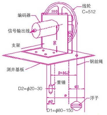
Figure 2 Float type water level measuring device
3.2 Encoder
According to the actual requirements of the field, the encoder uses the field bus output multi-coil absolute value encoder.
The absolute value encoder is determined by the mechanical position of the code, each code is unique and not repeated, it is not affected by power failure and interference, do not need to remember, do not need to find reference points, and do not need to count all the time, when the need to know the position, when to read, thus, the encoder's anti-interference characteristics and data reliability are greatly improved. Another advantage of multi-turn absolute value encoder is that due to the large measurement range, there is often more surplus in actual use. In this way, there is no need to bother to find zero points during installation and debugging, and a certain middle position within the measurement range can be used as the starting point, thus greatly simplifying the difficulty of installation and debugging.
Encoder signal output mainly includes parallel gray code output, serial ssi output, bus output, analog output of 4~20ma. The parallel gray code and analog output signals are easy to read but not suitable for long-distance transmission. The serial ssi output is mostly matched with the ssi module of Siemens plc with high cost. The field bus encoder transmits signals by means of communication, and the signal follows the physical format of rs485. The connection line is less, the transmission distance is long, and the protection and reliability of the encoder is improved. Signal receiving device only needs one interface, can read multiple encoder signal, multiple encoder centralized control can greatly save the cost.
3.3 plc of water level measurement and control device
plc choose m340 modular plc, it is Schneider company production of high performance and price ratio of programmable controller, has been widely used in various fields of industrial control. The cpu module uses the bmx p34 2020 with high performance and large memory, with a 100m Ethernet and a 485 serial port. The input and output modules can be flexibly configured according to the actual requirements.
4 Software Design
4.1 Programming Steps
plc hardware configuration, control program using Schneider's programming package unity pro to complete, pc through the network or usb and m340 plc program transmission. First of all, plc hardware configuration, including the base, power supply, cpu, input and output module. You can view the power usage by viewing the power module properties. Reserve a certain capacity; otherwise, you need to replace a power module with a larger capacity. In the serialport port of the cpu module, set serial link parameters such as 485 modbus master station, baud rate 9600, frame delay 4ms, data bit 8, stop bit 1, and parity check. Create network link ethernet1 and configure network communication parameters such as the ip address. Connect the ethernet port of the cpu module to network link ethernet1. Configure analog output module parameters according to the field analog signal requirements; Define relevant variables, etc.
4.2 plc program design
(1) Program structure. The program adopts modular design with high readability and maintainability. The program structure is shown in Figure 3.

Figure 3 Program structure diagram
(2) Program notes. plc is powered on for the first time to scan the init() subroutine, initialize the communication parameters, preset values of upper and downstream altitudes, zero values of each sensor, and differential pressure setting values of the grid, etc.
comm() subroutine for sensor communication reads the sensor water level value at a time interval, and maintains the original value when communication fails.
calc() subroutine is calculated to calculate the actual elevation value of upstream and downstream, behind the sewage barrier, the sewage barrier pressure difference, the available water of each unit and so on.
Signal output out() subroutine, sewage grid pressure difference is too large alarm, communication fault alarm, device fault alarm, 4 ~ 20ma analog output, etc.
Data sent() subprogram, according to the communication protocol of monitoring host computer, organize data messages, including the actual altitude value, effective water head, detailed fault information, sewage grid differential pressure alarm value.
4.3 Reading water level signal
m340 plc and encoder serial rs485 communication using modbus rtu communication protocol, this communication protocol has been widely used by various industries at home and abroad as a general industrial standard protocol for system integration, is conducive to the maintenance and expansion of the system. plc is the master station, encoder is the slave station.
According to the technical manual of the encoder, the modbus address of the water level measurement is 4x0000. According to the information frame structure of the modbus communication protocol, the water level measurement value of the sensor at address 1 should be read. The following communication code should be sent: m340 plc uses read_var function module to read the water level information:
01 03 0000 0001 840a
Station address function code Number of addresses first crc verification code
Function Module description [1]
adr
Correspondence address: The syntax is addm (' r.M.c.ode 'rack number. Module ID. Channel ID. Station address) type.
obj The type of the object to be read
'%m' : indicates the internal bit
'%mw' : internal word
'%s' : indicates the system bit
'%sw' : indicates the system word
num Indicates the index of the first object read.
nb The number of objects to be read.
recp output parameter A word table containing the values of the read object.
gest Exchange Management Table: an array of 4 words.

Table 1 Switch management table

Figure 4 read_var function module
In Figure 4, the read_var function module can send the water level value of the sensor at address 1 into %mw1, and the exchange management table is placed at % mw400:4, %mw401==0, indicating that the communication is successful and the fault code is recorded with non-zero value. The communication process requires a certain amount of time to ensure reliable communication and prevent communication blocking. The communication of the four sensors is carried out in time sharing and triggered by the rising edge. Read the switch management table to confirm whether the communication is successful. If the communication fails, the fault code should be sent to the upper computer and an alarm should be given. The water level value should be kept as the value read during the last correct communication.
4.4 Design of monitoring software for upper computer
The host computer system and plc are connected through Ethernet. The computer monitoring system of Shuidong Power Plant adopts nc2000 system of Nanrui Group Company. nari nc2000 computer monitoring system is a new generation of computer monitoring system software for the field of water conservancy and hydropower of Nanrui Group [2]. nc2000 has good man-machine interface and network function, and uses tcp/ip modbus protocol for network communication with Schneider plc. In the configuration environment, the designer drives the plc configuration, the operating environment monitors the water level information and the fault alarm with the man-machine interface in the form of graphics, stores the history database of the relevant data, generates the report, and makes use of the web function to make the system with the online monitoring function, that is, under the condition of authorization, the system can be remotely monitored with a standard browser on any computer connected to the Internet. Limited by space, the upper computer program will not be detailed.
5 Closing Remarks
The design structure of the system is reasonable. The multi-circle absolute encoder is used to collect the water level. The programmable controller is the control core, which improves the automation degree of the system and ensures the reliability of the system operation. The modular design of hardware and software has good expansibility and flexibility, and can change the system configuration scale according to the actual requirements of the field. The system has been running stably in Shuidong Power Station, Fujian Province. It can meet the operation requirements of the power station in monitoring and alarm, comprehensive calculation, signal output and other aspects. It has achieved good results and has high promotion value.
www.xbplcdcs.com