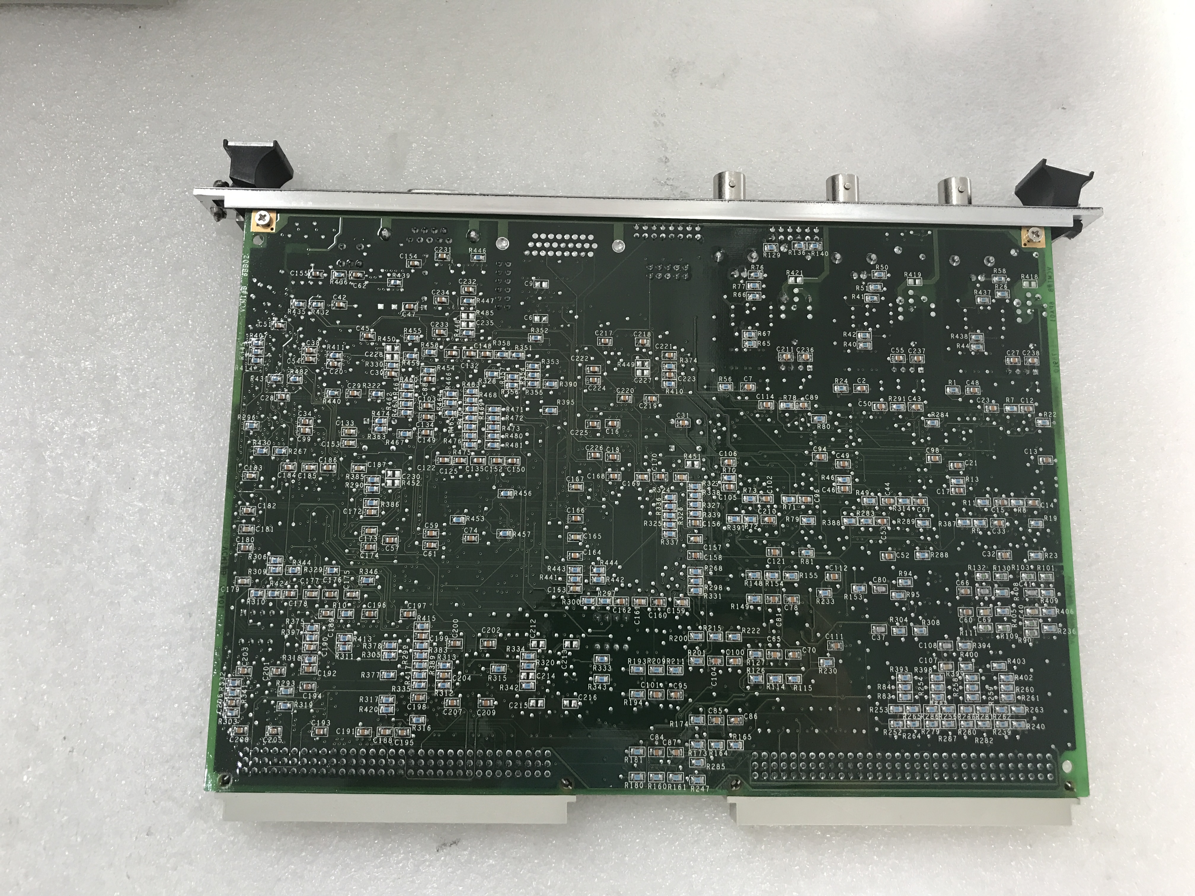
Product Description
The GE Contactor Driver Board DS200CDBAG1 opens and closes a contactor.Before you touch the board make sure you remove power to drive and test the board to make sure no power is in the board. Also, do not remove the board while the drive is receiving power. Static electricity can damage a board. Use a grounding strap to work on the board and store the board in a static protective bag.
The DS200CDBAG1 has one jumper. JP1 is a 3 pin jumper and it used only for factory testing purposes. Keep pins 1 and 2 covered for normal operation. When pins 2 and 3 are covered, it is reserved only for factory use.The DS200CDBAG1 also features a potentiometer that is used to control the amount of current applied to the contactor coil. This is set at the factory and it is best practice to not change it.
The DS200CDBAG1 also has test points you can use for testing the operation of the board. One test point is the common reference point for the board. One test point is the 15V DC test point as referenced to the common reference point. One test point is for the contactor driver reference voltage.
The connector 1TB on the DS200CDBAG1 board consists of four sections (1TBA, 1TBB, 1TBC, and 1TBD). Carefully note the locations of the connectors on the board and use a screwdriver to pry apart the sections. The replacement board might have the connectors in different locations so care must be taken to plug the sections into the correct connectors.