Product Description
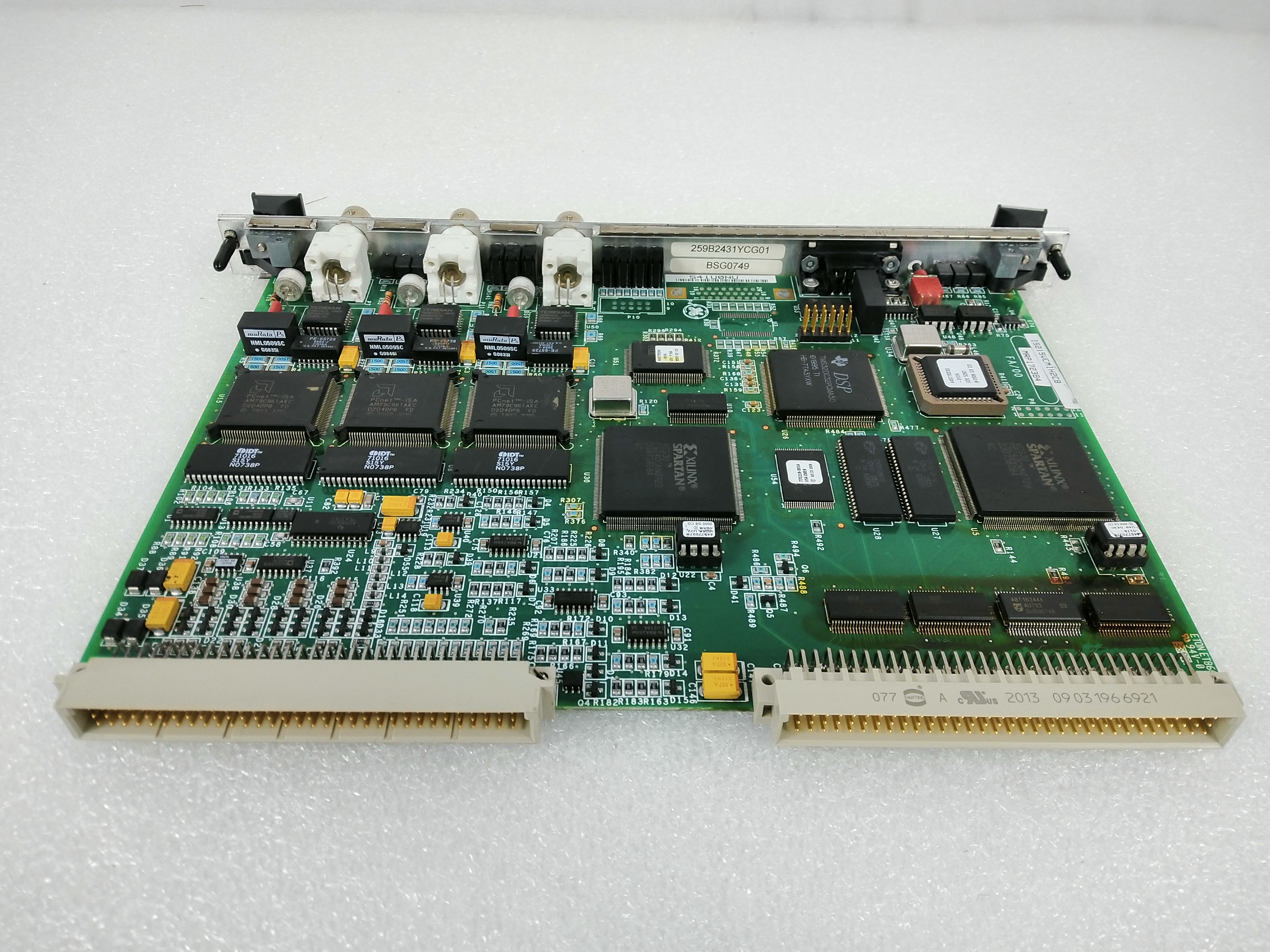
The GE Firing Circuit Control Board DS200FCRLG1A features 27 bayonet-type connectors. It is also populated with 27 jumpers, 1 34-pin connector, and 1 9-pin connector. The 27 bayonet connectors are connected to matching pins that are attached to the ends of the signal and power cables. The cables are also connected to other devices and boards in the drive. To install a cable in the bayonet connector, align the pin with the connector and press it into place. Press the cable until it is firmly connected and it clicks into place.
To disconnect a cable from the bayonet connector, hold it by the connector at the end of the cable and pull it out of the connector. Do not tug the cable out by holding the cable. This might cause the signal wires to dislodge from the connector end.
With multiple wires, cables, and ribbon cables connected to the board, you must consider proper cable routing. One consideration is that the signal wires must be routed separately from the power cables. The power cables radiate interference that can make the signals carried to and from the board useless. Route the signal wires as far away from the power cables as possible. Or, limit the space the signal and power cables are routed near each other. The more current that the power cables carry, the shorter the distance should be that the signal and power cables are routed together. In some circumstances, you can use shielded cables to protect the signals from the power cables.