
DS200GGDAG1 Technical Specifications
| Manufacturer | GE General Electric |
| Series | Mark V |
| Part Number | DS200GGDAG1 |
| Product Type | GTO Gate Driver Board |


Contact: YMGK Industrial Control
Phone: +86 18059884790
E-mail: plc66@qq.com
Add: whatsapp+86 18059884790
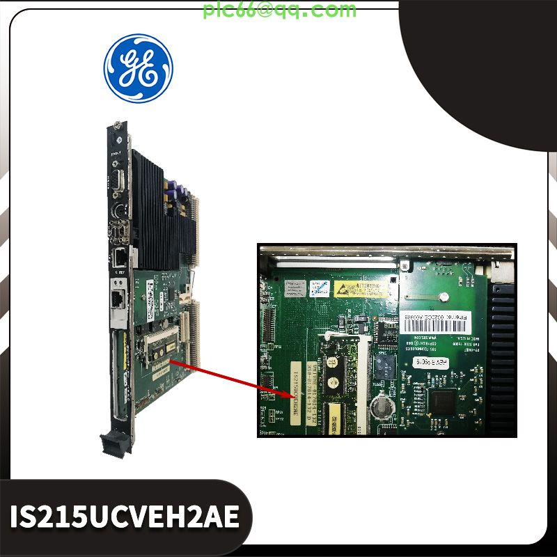
The GE GTO Gate Driver Board DS200GGDAG1 features 2 3-pin connectors and 2 bayonet connectors. The GE GTO Gate Driver Board DS200GGDAG1 also contains 2 sets of 4 LEDs. Each set has 1 red LED, 1 amber LED, and 2 green LEDs. The bayonet-type connectors on the board require some special consideration when you replace the board. To disconnect them from the board, hold one by the connector and pull it away from the board. Only hold the cable from the connector portion and not from the cable. You might damage the cable by pulling the wires out of the connector. This is especially true because of the plastic retention clips that hold the bayonet cable in the connector.
When you insert the bayonet cable in the connector, align the bayonet with the connector and press it into the connector. Make sure it is fully seated and that the retention clips have firmly secured the cable. When you insert the bayonet, the retention clips click into place over the cable.
The two sets of LEDs on the board display the same information. One set is viewable from the side of the board and the other set is viewable looking down on the board. The LEDs provide information concerning the health of the board. The two green LEDs are lit when the board is processing normally and the AC LED flashes to indicate when activity is occurring. The red LED is on when a fatal error has occurred. The amber LED is lit as a warning that a non-fatal error has occurred.
Tel:+86 18059884790
E-mail:plc66@qq.com
E-mail2:+86 18059884790
Address:whatsapp+86 18059884790

Copyright © Xiamen Xiongba E-Commerce Co., Ltd.