Featured
Contact Us
Contact: YMGK Industrial Control
Phone: +86 18059884790
E-mail: plc66@qq.com
Add: whatsapp+86 18059884790
- Warehouse: Spot
- Warranty: 365 days
- Quality: Original module
- Condition: New / Used
- Shipping method: Courier delivery
- Contact person: Linda
- Contact number: +86 18059884790
- WeChat:18059884790
- E-mail: plc66@qq.com
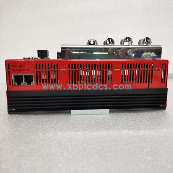
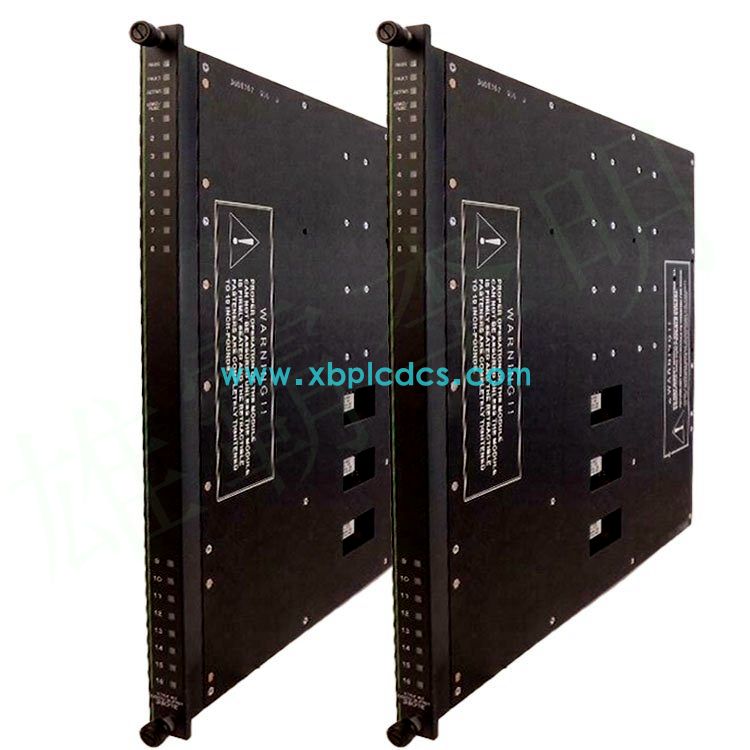
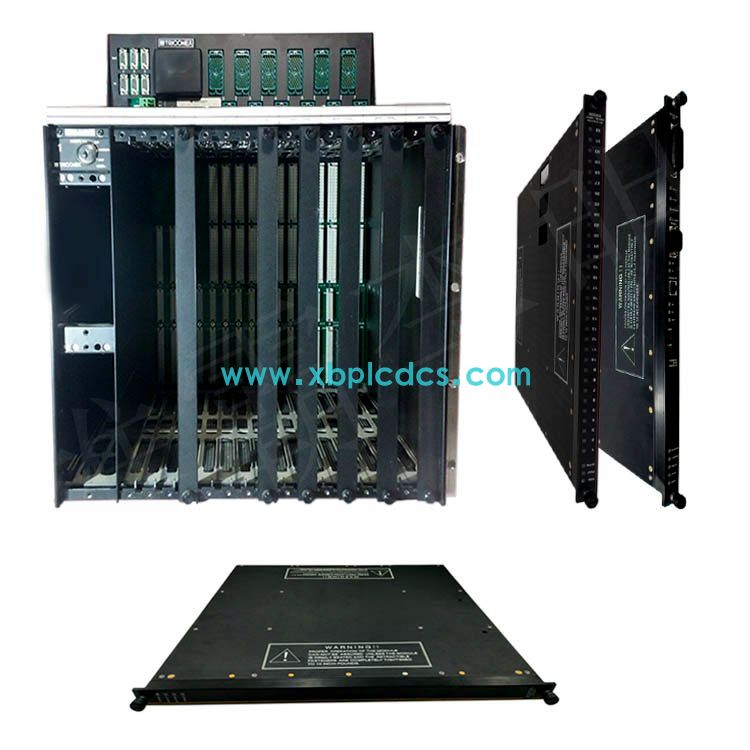
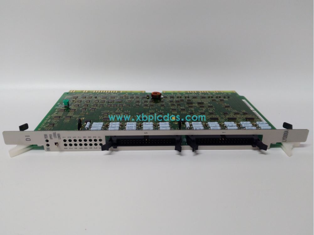
PS6548 HITACHI control module PS6548 HITACHI control module PS6548 HITACHI control module
What are the braking methods of induction motor? What are the characteristics of each? Which braking method is the speed relay used?
There are two kinds of braking methods of induction motor: mechanical braking and electrical braking. The common methods of mechanical braking are: electromagnetic lock brake and electromagnetic clutch brake. The commonly used braking methods are energy consumption braking, reverse braking and feedback braking.
The advantages of reverse braking are: strong braking force, rapid braking. Disadvantages are: poor braking accuracy, strong impact in the braking process, easy to damage the transmission parts, brake energy consumption is large, not often braking. Therefore, the reverse braking is generally applicable to the braking requirements of rapid, large inertia system, not often start and brake occasions.
The advantages of energy consumption braking are accurate, stable and less energy consumption. The disadvantage is that the additional DC power supply device is needed, the equipment cost is high, the braking force is weak, and the braking torque is small at low speed. Therefore, energy consumption braking is generally used for occasions requiring accurate and smooth braking.
1. Overview of stepping Cis control:
A control process can be divided into several stages, which are called states or steps. States are separated from each other by transition conditions. When the transition conditions between two adjacent states are satisfied, the state transition is realized. A state transition with only one direction is called a single-process CIS structure.
2. FX series PLC status element
Each state or step is represented by a state element, S0 is the initial step, also known as the preparation step, indicating whether the initial preparation is in place. The others are working steps.
State element is the basic element of state transition graph and one of the soft components of programmable controller. FX2N has a total of 1000 state elements, whose classification, numbering, quantity and usage are shown in Table 1.
www.xbplcdcs.com