Featured
Contact Us
Contact: YMGK Industrial Control
Phone: +86 18059884790
E-mail: plc66@qq.com
Add: whatsapp+86 18059884790
- Warehouse: Spot
- Warranty: 365 days
- Quality: Original module
- Condition: New / Used
- Shipping method: Courier delivery
- Contact person: Linda
- Contact number: +86 18059884790
- WeChat:18059884790
- E-mail: plc66@qq.com
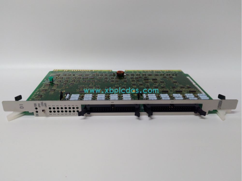
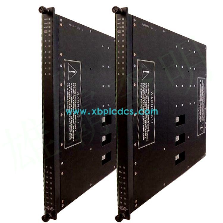
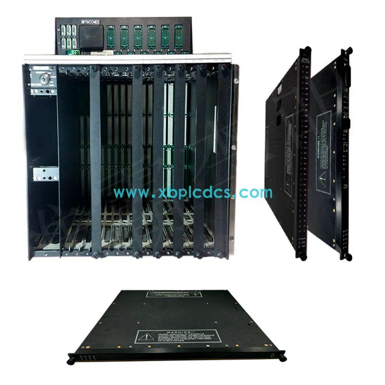
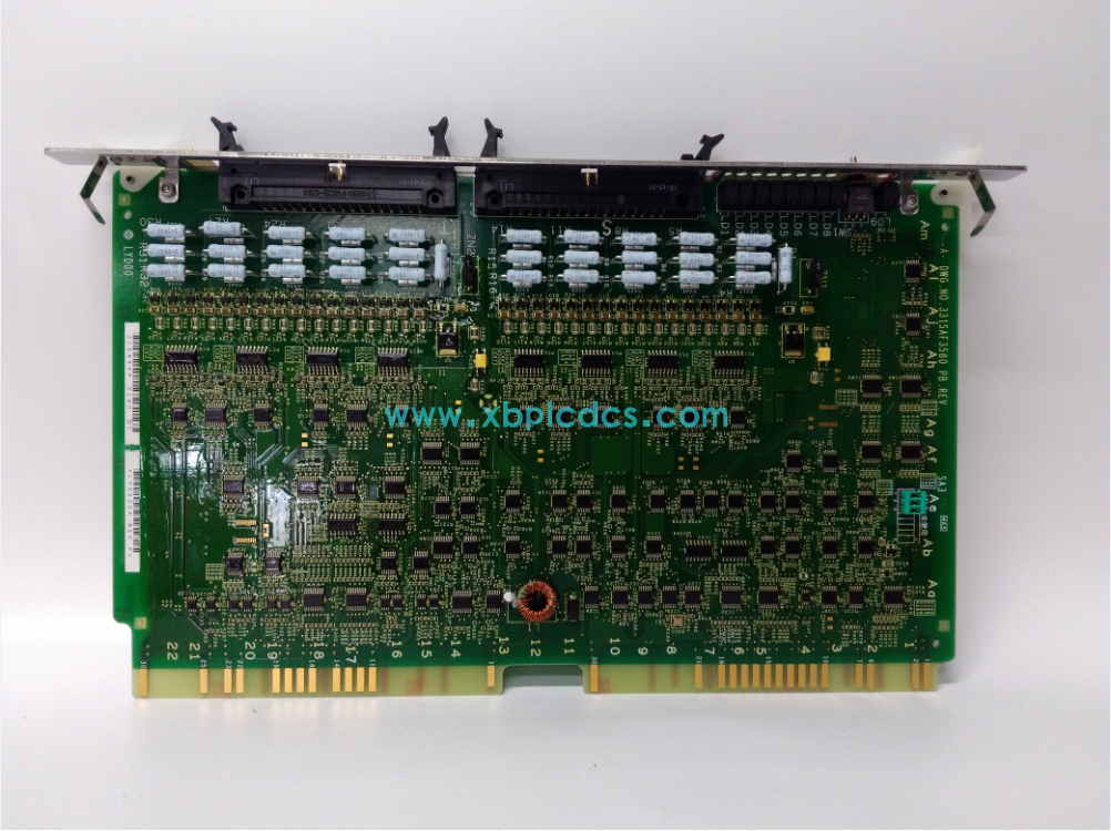
LUD060A HITACHI controller module
LUD060A HITACHI controller module
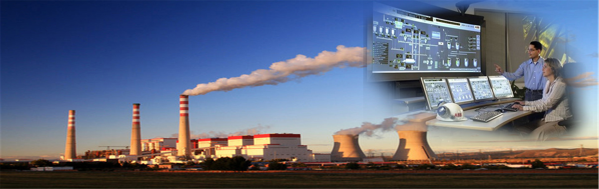
In order to alleviate the current situation of serious shortage of electric power supply, many large capacity thermal power plants have been put into construction and use all over the country. Therefore, the demand for coal is more and more large, and the automatic control requirements for coal transmission and other public systems are also higher and higher.
The automatic control system of 2×600MW unit in a Shanxi power plant is composed of two kinds of control equipment: the main control part (including boiler, steam engine and generator, etc.) uses the DCS control system of HONEYWELL Company; The Contrologix5000 series PLC system manufactured by ROCKWELL is used for the common parts (including coal transport, water treatment and ash removal, etc.). iFix3.5 is used for the upper software, and the data is connected to the DCS system via Ethernet so that the system can be operated on the coal transport program control PC. And can be operated on DCS.
The main function of the coal transport system is the process of transporting the coal to the coal dump ditch and the coal dump ditch through a series of transport equipment to the original coal bunker.
Due to the large capacity of the generating units in this power plant and the fact that two units share a set of coal transport system, the demand for coal is very large. In order to avoid one coal access road becoming a bottleneck and delaying normal production, two coal access roads are designed, with one way running and one way being standby, or the two roads can run simultaneously, respectively transporting coal to two different destinations.
2. Control equipment
The control objects of this coal transport system are: 21 belt conveyor (5# A and 7# A belt can run bidirectional), 2 bucket wheel pile and reclaimer, 2 roller screens, 2 ring type coal crusher, 2 clean water pumps, 30 vibrators, 2 wipers, 16 electric tees, 2 coal samplers into the furnace, 15 dust collectors, 6 impeller coal feeders, 2 disk-type electromagnetic iron remover, 8 sets of belt electromagnetic iron remover, 2 sets of belt sampling device, 2 sets of unloading truck, a total of 114 sets of equipment.

All the input and output signals of the program control system are isolated by relays to improve the anti-interference ability of the system and protect the PLC module to avoid damage due to the entry of large current signals.
This coal transport system adopts 16 electric three-way baffle, in order to make the system combination more flexible and diverse. When some equipment is faulty and needs maintenance, it can use other equipment to adjust the path of the three-way baffle to bypass the faulty equipment and continue loading coal, so that the whole system will not be paralyzed by the failure of one or several equipment.
3. Device control mode
The control modes of the equipment are as follows:
1) Experimental mode: manual operation mode. This mode is to open, close, start and stop a single device on the upper computer. The interlocking relationship between devices has been removed, and there is no link jumping function. Therefore, it cannot run with load in this mode.
2) Centralized interlocking manual: This mode is to start the equipment in the process to be started one to one according to the direction of reverse coal flow and stop one to one according to the direction of forward coal flow. It requires that the three-way baffle must be started in place before the equipment starts, and the protection action processing of the equipment is the same as the automatic control mode.
3) Automatic mode: It is a normal operation mode to start or stop the relevant equipment according to the pre-set process, which requires that the on-site equipment must be in normal state. Automatic mode is the best control mode of the system. In this mode, the equipment has the shortest no-load operation time and the operator has the least operation steps.
4) Local mode: Press the automatic selection button on the local operation box to the local position, and issue the start, stop or switch command from the operation box to realize the control of the field equipment. In this way, PLC has lost the function of controlling this equipment.

a) Upper computer system
This system is equipped with two upper computers, both can be used as operator station, one of them can be used as engineer station, and two industrial computer can be mutually standby. The upper computer is connected to the Ethernet switch with shielded twisted pair, and communicates with the PLC host through the Ethernet module. All data display and operation can be completed in the upper computer, and there are alarm, historical trend and report function, to provide the operator with the most complete use environment.
b) Control system
This system uses two 1756-L55M13 cpus, memory 1.5M. The two cpus are installed on the two racks respectively and are hot spares for each other. The CPU powered on first is the active CPU. In order to avoid power loss at the same time, the power supply of the two racks is respectively from the plant power supply and the UPS power supply. The programs in the two cpus are exactly the same. The primary CPU collects information, processes programs, and issues commands, while the standby CPU tracks the work of the primary CPU in real time. If the primary CPU is powered off or the communication is interrupted, the standby CPU takes the place of the primary CPU.
The host is connected with the PC through the Ethernet network for data exchange, and the following three local I/O racks are connected with the master station through the ControlNet network (ControlNet network is redundant configuration). The CPU determines the input signal collected, and then issues commands through the output module after calculation and processing through the pre-programmed program. To achieve the purpose of control.
c) Remote systems
The system provides an I/O remote station, which is connected to the I/O rack of the main station through multi-mode optical cable. This application method greatly reduces the number and length of control cables, reduces the grounding or wiring failures caused by too long cables, and also reduces the cost of input. In addition, the optical cable is used to connect the remote station communication mode, so that the communication distance is much longer than the application of coaxial cable communication, and eliminate the interference of voltage and current, improve the quality of data transmission.
d) Communication with other systems
Ethernet communication with DCS system, the use of optical cable to connect two switches, DCS can easily read the required data directly from the PLC host.
With the bucket turbine system and rail scale system communication is also used to connect the two switches of optical cable, because the coal transport system itself is more dispersed, the distance is relatively far (coal transport control room distance from the rail scale control room is more than 3 kilometers), the use of ordinary cable or multi-mode cable without repeater simply cannot meet the requirements, and the use of single-mode cable is simple, The longest communication distance without repeater can reach tens of kilometers.
e) Industrial television system
A total of 4 sets of industrial TV placed in the front of the industrial TV screen, through the camera lens the operation of the corresponding equipment and the accident situation displayed on the screen, and can be recorded through the computer storage, so that at any time in the future you want to see the picture of the period of record, analyze the cause of the accident. Four industrial TVS can display up to 16 pictures at the same time through screen segmentation technology. By selecting buttons, the pictures can be adjusted to the place where they want to observe for monitoring.